
Phase and amplitude modulation of baseband signals

Inactive Publication Date: 2002-07-02
APPLE INC
View PDF5 Cites 44 Cited by
  • Summary
  • Abstract
  • Description
  • Claims
  • Application Information

AI Technical Summary

Benefits of technology

Advantageously, the more power-efficient design leads to longer battery life where the present invention is employed in mobile handsets.
Advantageously, the present invention does not require highly-linear power amplifier circuits, thereby reducing manufacturing costs.

Problems solved by technology

As a consequence, power amplifiers, for example in wireless telephone handsets, tend to exhibit poor power-added efficiency with a resultant high DC power consumption and short battery life for the handsets.
Such amplifier linearization techniques are highly complex and thus suitable for use only in base stations.
They are generally too complex and expensive for use in handsets.

Method used


Image

  • Phase and amplitude modulation of baseband signals
  • Phase and amplitude modulation of baseband signals
  • Phase and amplitude modulation of baseband signals

Examples


first embodiment

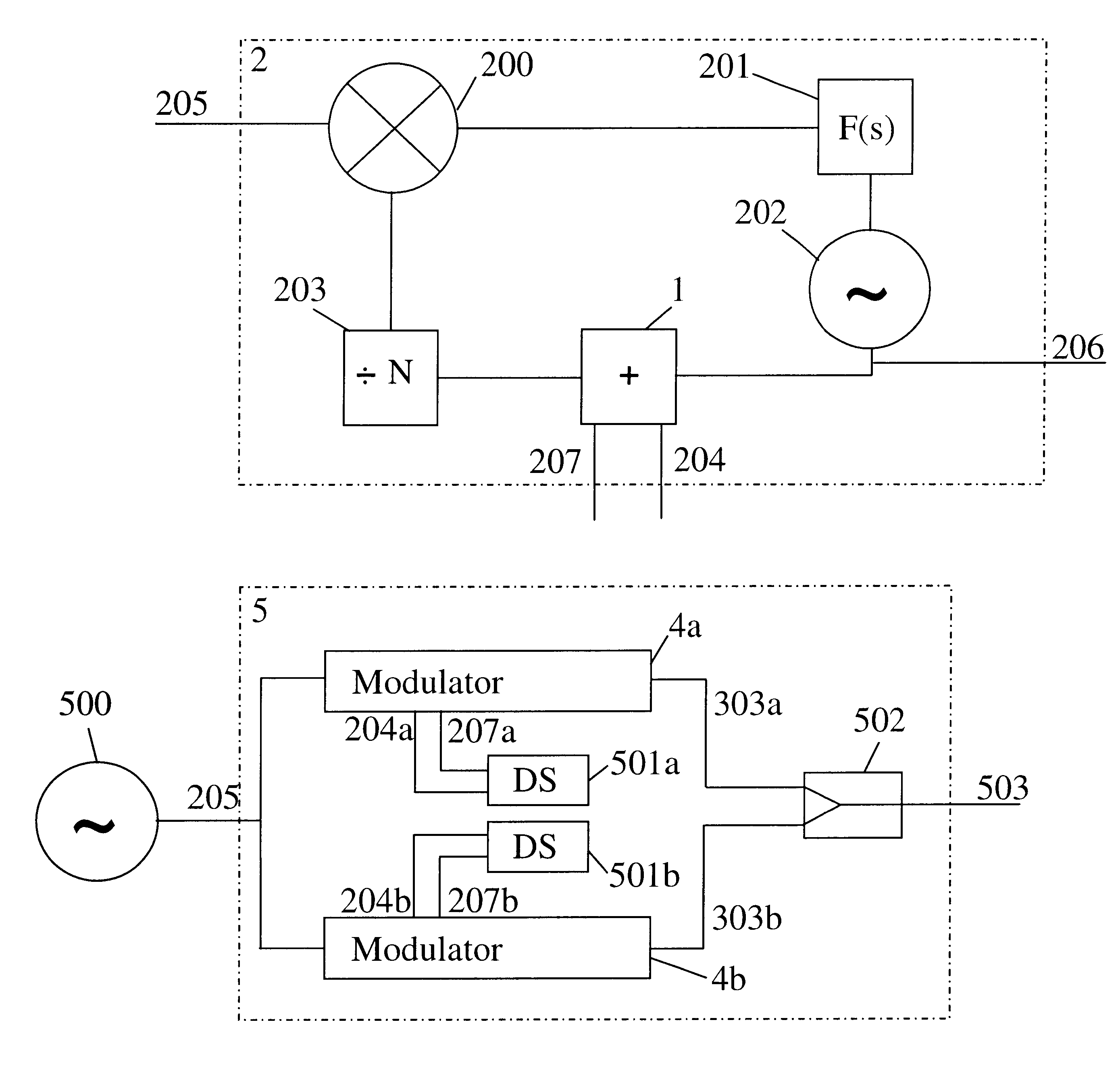
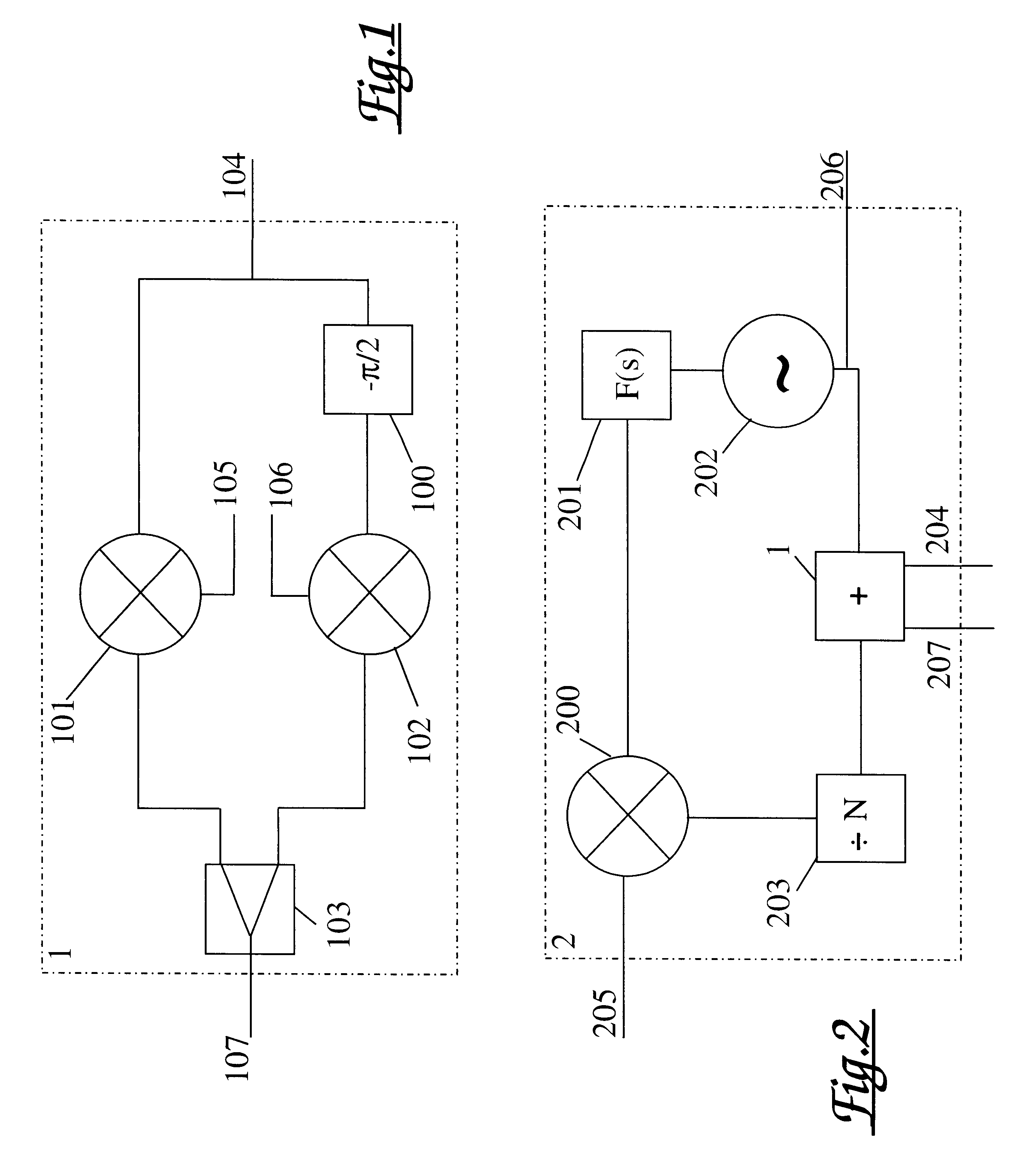
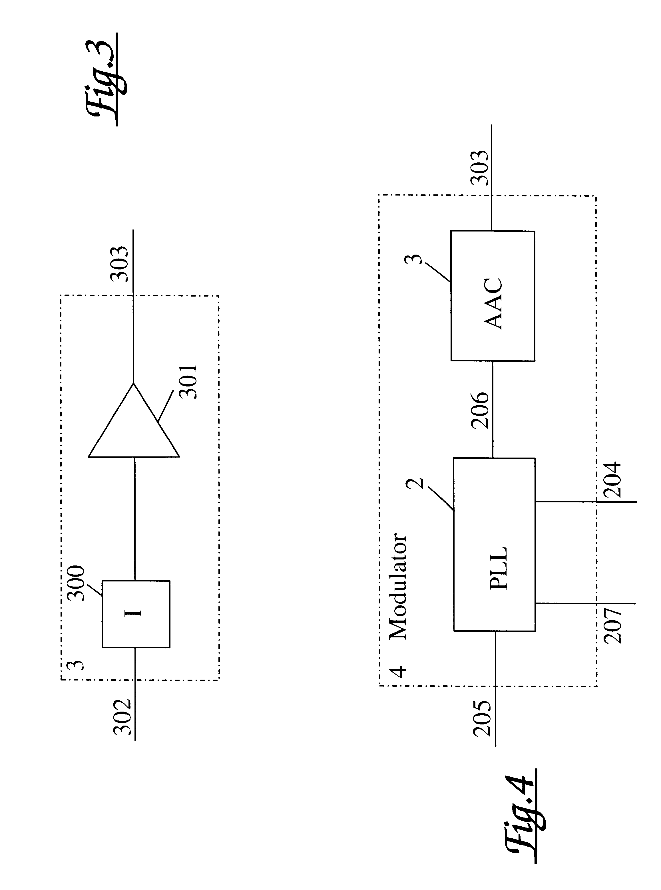
a phase and amplitude modulator in accordance with the present invention, shown in FIG. 5, comprises a common source (500) of a reference signal, first and second PLL modulators (4a, 4b) (for example that of FIG. 4), and a signal combiner (502).

The reference signal (205) fed to each modulator is provided from the common reference source (500). Each modulator (4a, 4b) also receives a data signals (204a, 204b, 207a, 207b) from data source (501a, 501b) respectively. The phase-encoded output signal (303a, 303b) from each modulator is fed to the signal combiner (502) where they are combined to provide a phase and amplitude modulated output signal (503).

The signal (503) output from the signal combiner is a phase and amplitude encoding of the two data signals (204a, 204b) received by the respective modulators.

The common reference source (500) may, for example, comprise a reference oscillator also with programmable dividers and these, in conjunction with the PLL divider (203) in each modula...


PUM


Abstract

A baseband signal modulator provides a phase and amplitude modulated carrier signal. First and second phase modulators each receive a common reference signal and derive therefrom a carrier signal frequency. The phase modulators each receive a respective pair of phase-encoded data signals so as to provide respective first and second phase-encoded carrier. The modulator outputs are summed to provide the phase and amplitude modulated carrier signal. Each phase modulator includes a respective phase locked loop incorporating an oscillator locked via the common reference signal to the carrier signal frequency, and a phase adder having a first input for receiving the carrier frequency signal and having second and third inputs for receiving the respective pair of data encoded signals.

Description

The present invention relates to a method and apparatus for phase and amplitude modulation of a baseband signal and a system incorporating the same.In particular, the present invention relates to a method and apparatus for phase and amplitude modulation of a digital signal and a system incorporating the same.BACKGROUND TO THE INVENTIONDigital communication equipment is used in a wide variety of devices for the transmission of digital information. Such information includes numerical data in computers and digital encodings of voice in telecommunications systems.The majority of modulation formats involve impressing a time varying amplitude and phase characteristic onto a carrier wave in a predetermined manner whereby there is a fixed relationship between the information that the signal is to carry and the instantaneous values of the phase and amplitude. For a carrier as defined in equation (1):Carrier=Re[e .sup.j.omega.t ] (1)and the modulation defined by equation (2):Modulation=Re[r(t...

Claims


Application Information

Patent Timeline
IPC IPC(8): H03C3/00H03C3/40H03C5/00H03C3/09H04L27/20
CPCH03C3/0975H03C3/40H03C5/00H04L27/2017
Inventor EDWARDS, FRASER MURRAYBROWN, DAVID ALAN
Owner APPLE INC
Learn More