Fuel cell stack

a fuel cell and stack technology, applied in the field of fuel cell stacks, can solve the problems of fluid not being delivered uniformly for each of the fuel cell units, increasing pressure loss, and fuel not flowing smoothly through the communication hole, so as to reduce the pressure loss in the communication hole

Inactive Publication Date: 2002-07-09
HONDA MOTOR CO LTD
View PDF12 Cites 55 Cited by
  • Summary
  • Abstract
  • Description
  • Claims
  • Application Information

AI Technical Summary

Benefits of technology

A principal object of the present invention is to provide a fuel cell stack which makes it possible to reduce the pressure loss in the communication hole and uniformly deliver the fluid to each of the fuel cell units.

Problems solved by technology

The fluid such as the fuel fails to smoothly flow through the communication hole.
As a result, the pressure loss is increased.
For this reason, a problem is pointed out in that the fluid cannot be delivered uniformly for each of the fuel cell units.
However, such an arrangement enlarges the size of the stack, resulting in a problem that the entire system becomes large.

Method used


Image

  • Fuel cell stack
  • Fuel cell stack
  • Fuel cell stack

Examples


first embodiment

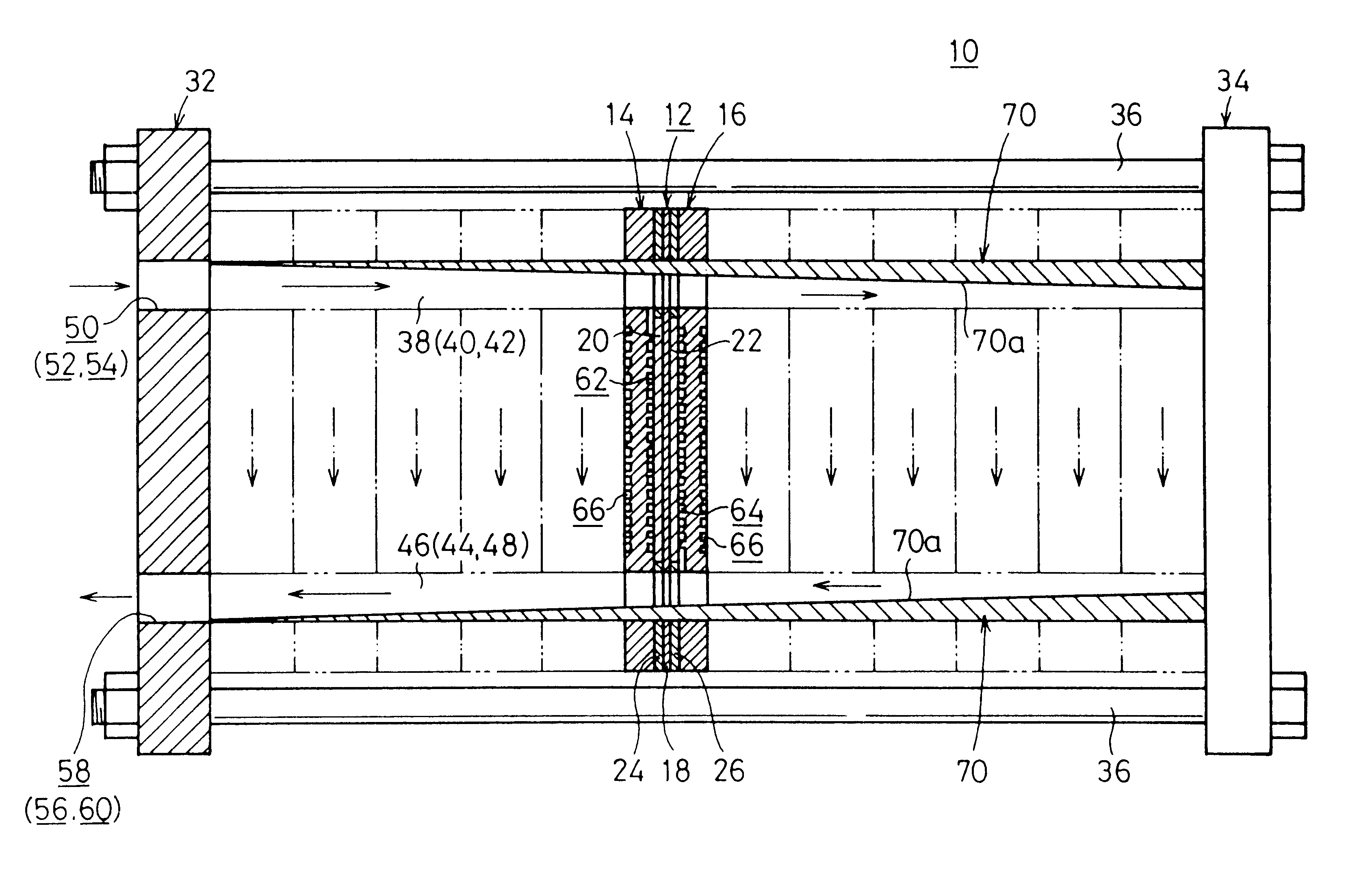
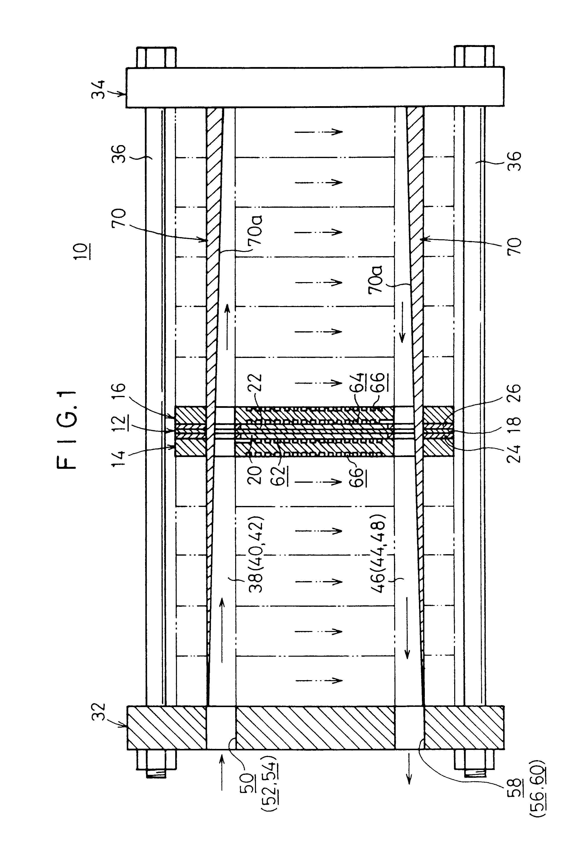
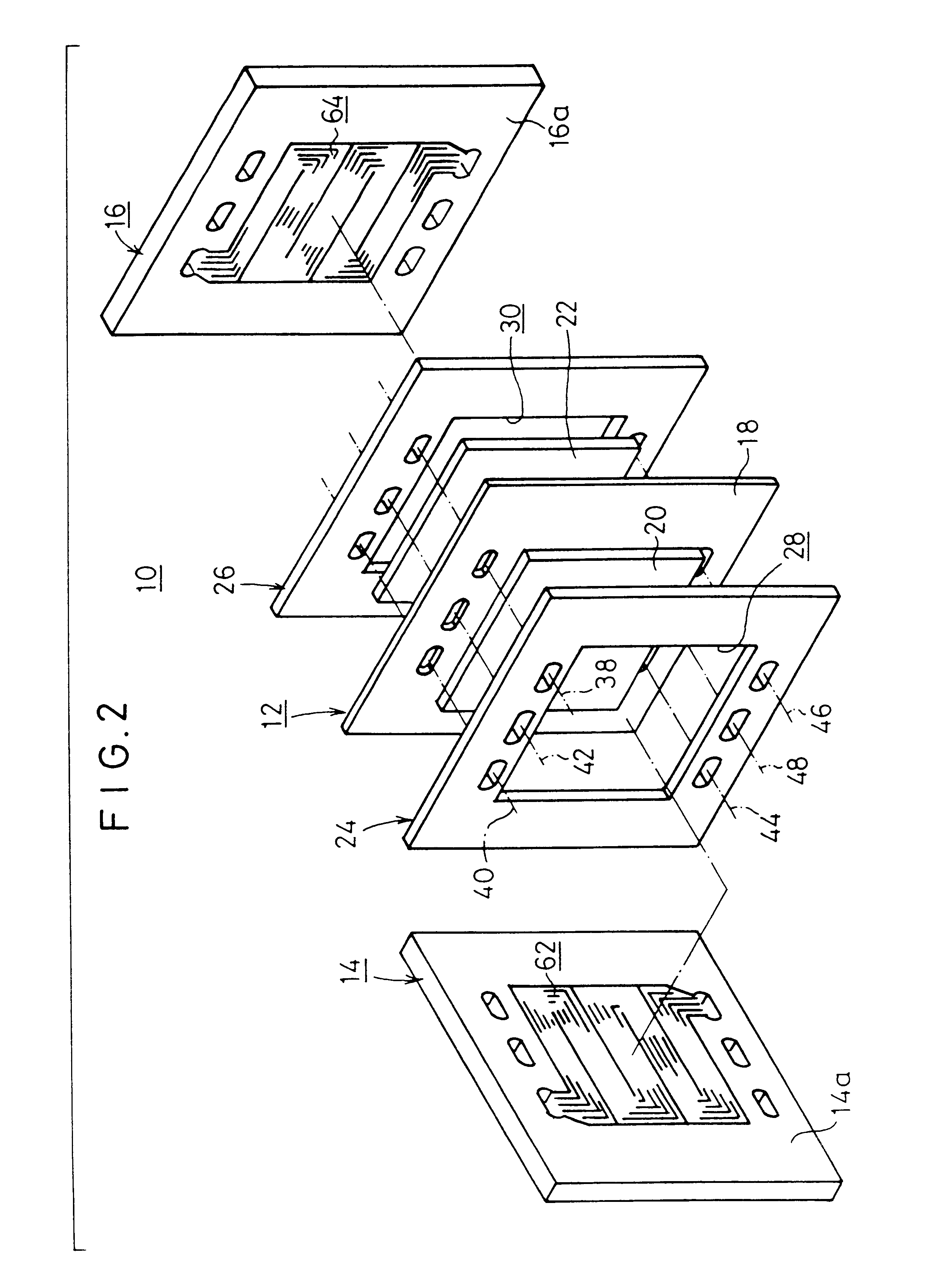
FIG. 1 shows a longitudinal sectional view illustrating major components of a fuel cell stack 10 according to the present invention, and FIG. 2 shows an exploded perspective view illustrating a part of the fuel cell stack 10.

The fuel cell stack 10 comprises fuel cell units 12 and first and second separators 14, 16 for interposing the fuel cell units 12 therebetween. A plurality of sets of these components are optionally stacked with each other. The fuel cell unit 12 includes a solid polymer ion exchange membrane 18, and an anode electrode 20 and a cathode electrode 22 which are arranged with the ion exchange membrane 18 interposed therebetween.

As shown in FIG. 2, first and second gaskets 24, 26 are provided on both sides of the fuel cell unit 12. The first gasket 24 has a large opening 28 for accommodating the anode electrode 20, while the second gasket 26 has a large opening 30 for accommodating the cathode electrode 22.

The fuel cell unit 12 and the first and second gaskets 24, 26 ...

second embodiment

FIG. 6 shows a perspective view illustrating a wedge member (insert member) 80 for constructing a fuel cell stack according to the present invention. The smoothing treatment such as the mirror finish is applied to a surface 80a of the wedge member 80 to make contact with the fluid such as the hydrogen-containing gas, in the same manner as in the first wedge member 70. The wedge member 80 includes guide sections 82a, 82b each having a circular arc-shaped cross section, the guide sections 82a, 82b being provided on both sides of the wedge member 80 to be inserted, for example, with respect to the both wall surfaces of the fuel gas supply passage 38.

Accordingly, for example, when the wedge member 80 is inserted into the fuel gas supply passage 38, the guide sections 82a, 82b are supported by the both wall surfaces of the fuel gas supply passage 38. Therefore, it is possible to reliably prevent the wedge member 80 from occurrence of any positional deviation in the fuel gas supply passag...

third embodiment

FIG. 7 shows a schematic perspective view illustrating a wedge member (insert member) 90 for constructing a fuel cell stack according to the present invention. The smoothing treatment is applied to a surface 90a of the wedge member 90 to make contact with the fluid such as the fuel gas. An irregular section, for example, a recess 92 is provided at an intermediate position of the surface 90a.

Accordingly, in the third embodiment, the opening cross-sectional area of the communication hole is enlarged at a central portion of the fuel cell stack corresponding to the recess 92 of the wedge member 90. The flow rate is decelerated at the recess 92, and the static pressure is increased. Therefore, when the wedge member 90 is installed to the cooling water supply passage 42, the following effect is obtained. That is, the flow rate of the cooling water can be increased especially at the central portion of the fuel cell stack at which the temperature tends to increase. Thus, the temperature dis...


PUM

PropertyMeasurementUnit
pressureaaaaaaaaaa
cross-sectional areaaaaaaaaaaa
power generationaaaaaaaaaa

Abstract

Disclosed is a fuel cell stack comprising fuel cell units and first and second separators which are alternately stacked with each other. Wedge members are integrally inserted, over the plurality of fuel cell units, into communication holes of a fuel gas supply passage, an oxygen-containing gas supply passage, and a cooling water supply passage, as well as a fuel gas discharge passage, an oxygen-containing gas discharge passage, and a cooling water discharge passage. A fluid is uniformly delivered to each of the fuel cell units by the aid of the wedge members. Accordingly, the fluid of any one of a fuel gas, an oxygen-containing gas, and a cooling medium is uniformly delivered to each of the fuel cell units. Further, it is possible to simplify the arrangement of the fuel cell stack.

Description

BACKGROUND OF THE INVENTION1. Field of the InventionThe present invention relates to a fuel cell stack comprising separators and fuel cell units each including an anode electrode and a cathode electrode with an electrolyte interposed therebetween, the fuel cell units and the separators being alternately stacked.2. Description of the Related ArtFor example, the solid polymer fuel cell is generally composed of a fuel cell stack comprising fuel cell units stacked with each other by being interposed by separators, each of the fuel cell units including an anode electrode and a cathode electrode which are arranged on both sides of an electrolyte composed of a polymer ion exchange membrane (cation exchange membrane).In such a fuel cell stack, the fuel gas, for example, a gas principally containing hydrogen (hereinafter referred to as "hydrogen-containing gas"), which is supplied to the anode electrode, contains hydrogen which is ionized on the catalyst electrode and which is moved to the c...

Claims


Application Information

Patent Timeline
Patent Type & Authority Patents(United States)
IPC IPC(8): H01M8/24H01M8/04
CPCH01M8/2465H01M8/04029H01M2300/0082Y02E60/50H01M8/2483
Inventor WARIISHI, YOSHINORIFUJII, YOSUKEOKAZAKI, KOJIYAMAMOTO, AKIOOKAMOTO, TAKAFUMITANAKA, MANABUSATO, SHUJI
Owner HONDA MOTOR CO LTD
Why Eureka
Try Eureka