Mechanically formed standoffs in a circuit interconnect

a technology of circuit interconnection and standoff, which is applied in the direction of electronic connection formation of printed elements, instruments, record information storage, etc., can solve the problems of solder covering bonding pads, causing the possibility of bridging adjacent joints, and the hard disk drive used in virtually every personal computer has traditionally been one of the most expensive components, etc., to achieve the effect of low cos

Inactive Publication Date: 2002-07-09
WILLIAMS STEPHEN P
View PDF17 Cites 12 Cited by
  • Summary
  • Abstract
  • Description
  • Claims
  • Application Information

AI Technical Summary

Benefits of technology

A general object of the present invention is to provide a mechanically formed standoff in a circuit interconnect to provide a low cost alternative to solder bumps.
The standoff provides a gap between itself and a corresponding bonding pad, thereby enabling sufficient solder to solidify therein between, resulting in a more reliable joint. The standoff may be formed with a punch and die assembly into any shape which provides the required gap. The mechanically formed standoff may also be covered with bonding material other than solder, e.g. gold, to accommodate other types of joints.

Problems solved by technology

The hard disk drive used in virtually every personal computer has traditionally been one of the most expensive components installed therein.
One drawback of this type of solder covered bonding pad occurs during the soldering process, and is illustrated in FIG. 1b.
The ejected solder creates the detrimental possibility of bridging adjacent joints.
However, the disadvantage of solder bumps 22 is that its fabrication in the flexure / conductor requires additional manufacturing steps, making the interconnects more expensive.
In addition, during processing, contamination in the area where the bump is electroplated can cause weak joints and potential reliability problems.
Resulting fractures at the electrical trace and solder bump interface have also been detected, creating reliability concerns.
Neither of these approaches are manufacturably desirable because neither approach is reworkable.

Method used


Image

  • Mechanically formed standoffs in a circuit interconnect
  • Mechanically formed standoffs in a circuit interconnect
  • Mechanically formed standoffs in a circuit interconnect

Examples


Embodiment Construction

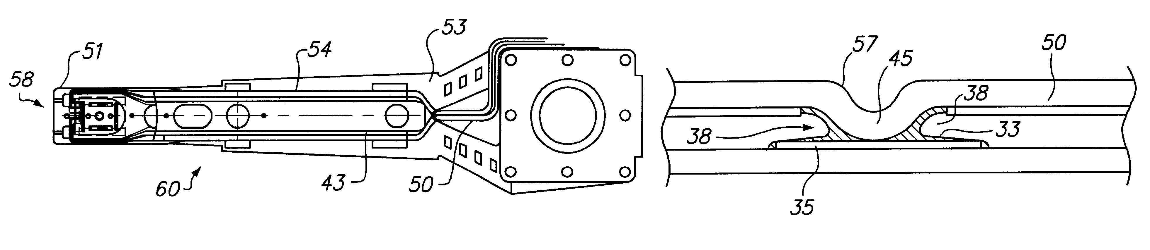
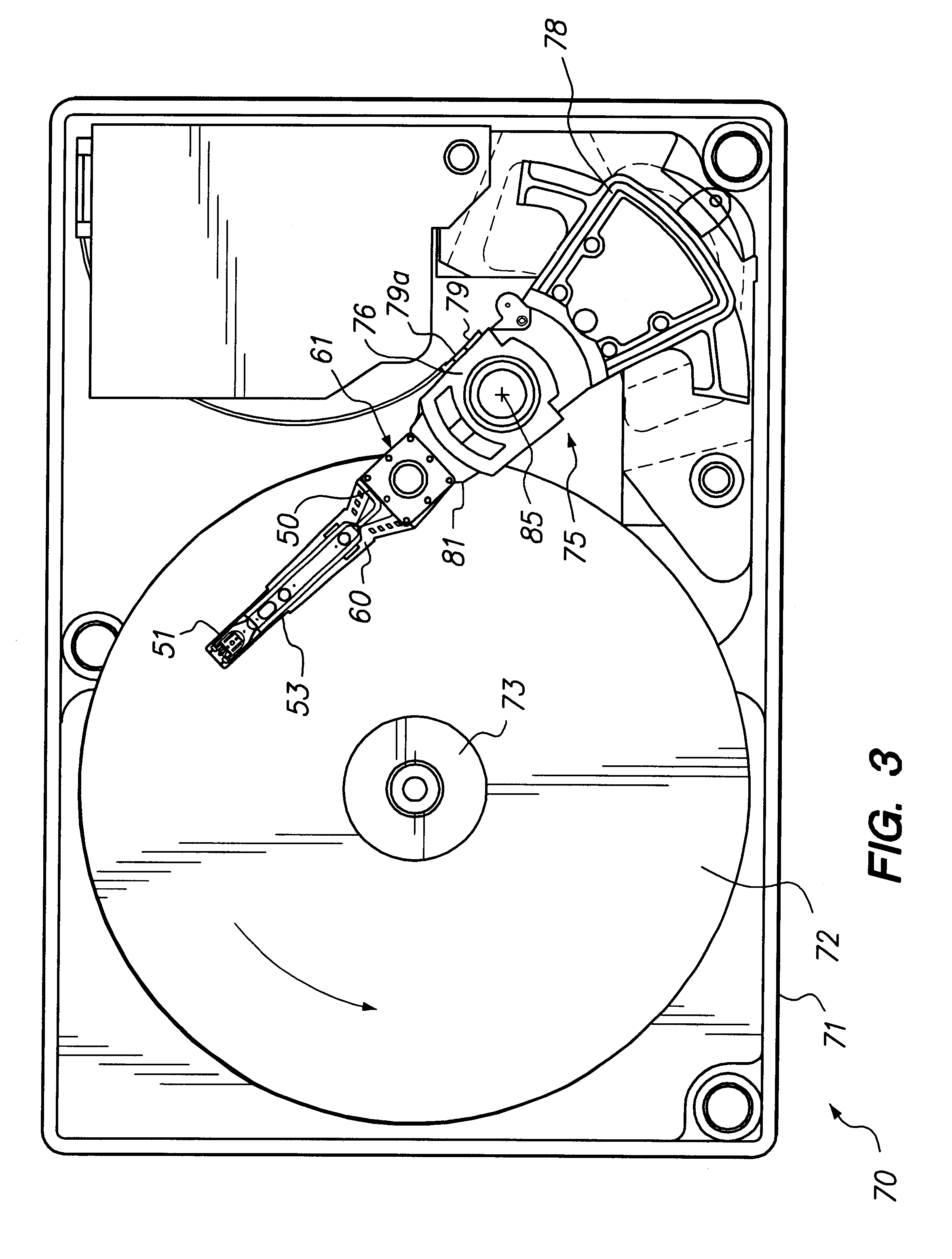
FIG. 3 shows a diagrammatic top plan view of the hard disk drive 70 including an integrated circuit interconnect 50 embodying principles of the present invention. Disk drive 70 includes a rigid base 71, supporting a spindle 73 (and a spindle motor, not shown) for rotating at least one data storage disk 72 in a direction shown by the curved arrow. Drive 70 also includes a rotary actuator assembly 75 rotationally mounted to the base 71 at a pivot point 85. The actuator assembly 75 includes a voice coil 78 which, when selectively energized by control circuitry 79, moves and thereby positions an actuator E-block 76 and head arms 81 and load beam assemblies 60 at radial track positions defined on the facing surfaces of storage disk 72. At least one of the load beam assemblies 60 is secured at its proximal end 61 to a distal end of head arm 81, e.g. by conventional ball-swaging techniques.

Conventionally, but not necessarily, two load beam assemblies 60 are attached to head arms 81 between...


PUM

PropertyMeasurementUnit
heightaaaaaaaaaa
standoff heightaaaaaaaaaa
thicknessaaaaaaaaaa

Abstract

Mechanically formed standoffs in a disk drive integrated circuit interconnect reduces the cost of manufacturing and improves the reliability of the electrical interconnections thereof. Connection pads defined along the interconnect are bonded with bonding pads of a signal producing source and a signal processing source. The standoffs provide mechanical stops during the bonding process, enabling sufficient bonding material to form between bonding areas. The standoffs are mechanically formed with a punch and die assembly either directly through a bonding pad predefined along traces on the interconnect or adjacent the bonding pad. The standoffs formed through the bonding pads are covered with solder or other electrically conductive bonding material.

Description

The present invention relates generally to standoffs for integrated circuit interconnect assemblies and methods for assembling the standoffs. More specifically, the present invention relates to standoffs mechanically formed onto a flexure / conductor structure for electrically interconnecting a read / write transducer head and a preamplifier integrated circuit assembly of a hard disk drive and the method for forming the standoffs.In the computer industry, there is a constant demand for products that are both less expensive and have higher performance. The hard disk drive used in virtually every personal computer has traditionally been one of the most expensive components installed therein. Thus, disk drive manufacturers have continuously tried to decrease the cost of their drives while at the same time increase the amount of mass storage provided.As is well known in the art, any rotating mass storage device includes at least one rotating disk, a read / write transducer deposited upon a sl...

Claims


Application Information

Patent Timeline
Patent Type & Authority Patents(United States)
IPC IPC(8): G11B5/48H05K3/36H05K3/40
CPCG11B5/4846G11B5/4853H05K3/363Y10T29/49144H05K2201/091H05K2201/10772H05K2201/2036H05K3/4007
Inventor WILLIAMS, STEPHEN P.
Owner WILLIAMS STEPHEN P
Why Eureka
Try Eureka