Differential pressure sensor

Inactive Publication Date: 2002-07-16
A THEOBALD
View PDF8 Cites 75 Cited by
  • Summary
  • Abstract
  • Description
  • Claims
  • Application Information

AI Technical Summary

Benefits of technology

An object of the present invention is thus to provide a pressure sensor which is simple to manufacture, low cost, capable of measuring very small differ

Problems solved by technology

Such effects constitute the main difficulty to be resolved in the manufacture of differential pressure sensors.
However, capacitance sensors present a certain number of problems.
One of the problems, which relates to the mechanical structure of the sensor, results from the very costly use of insulating material serving firstly to ensure sealing where each plate passes through the corresponding portions of the housing and to maintain the mechanical dimensions over the working temperature range, and secondly to ensure symmetrical setting of the plates, since the slightest variation in the distance between the plates and the membrane distorts measurement.
Another fundamental problem of that type of sensor results from the cabling which connects the sensor to the measurement device and which results in amounts of stray capacitance that are significant relative to the capacitances which vary over time as a function of pressure and of temperature.
Many instances of

Method used


Image

  • Differential pressure sensor
  • Differential pressure sensor
  • Differential pressure sensor

Examples


Embodiment Construction

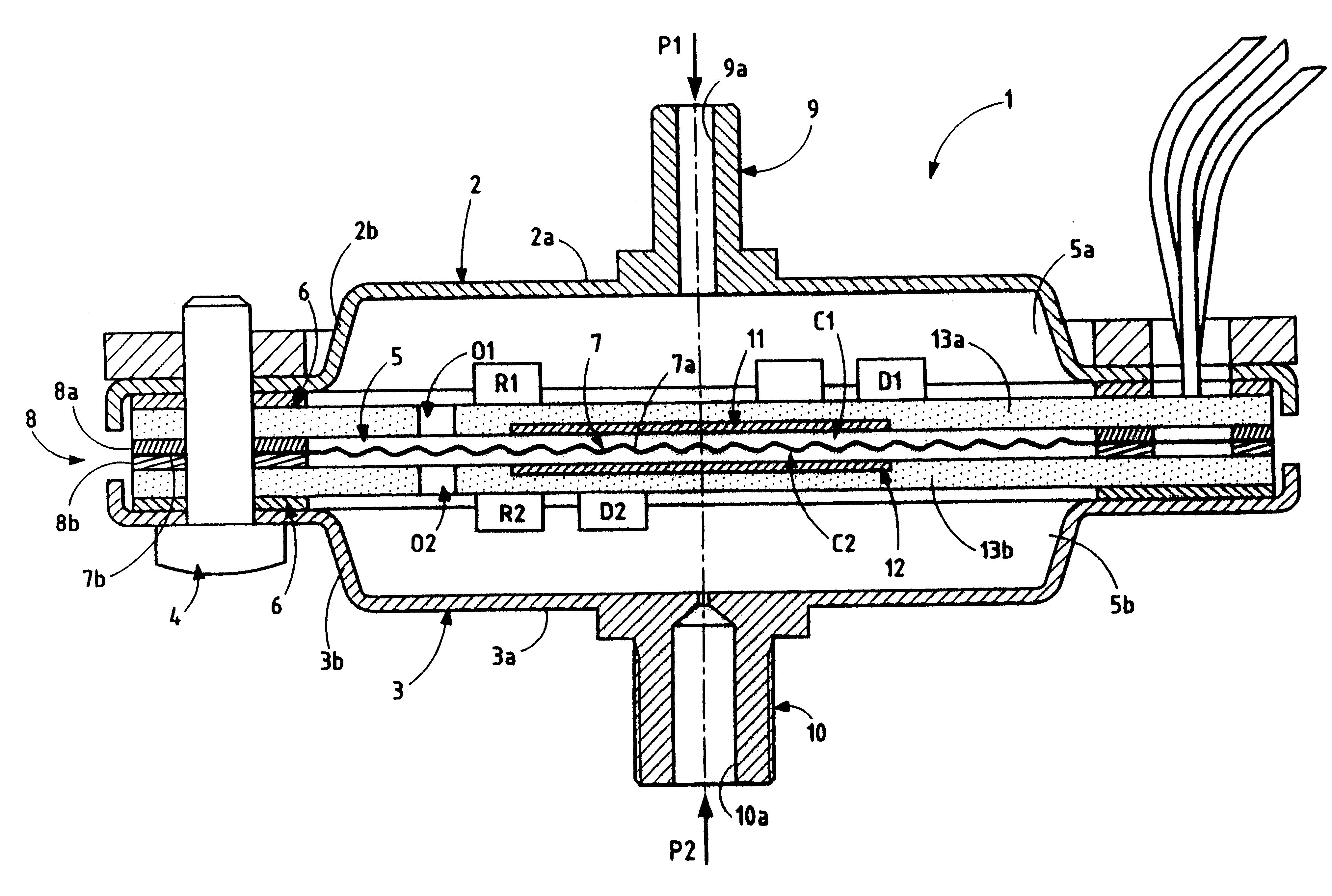
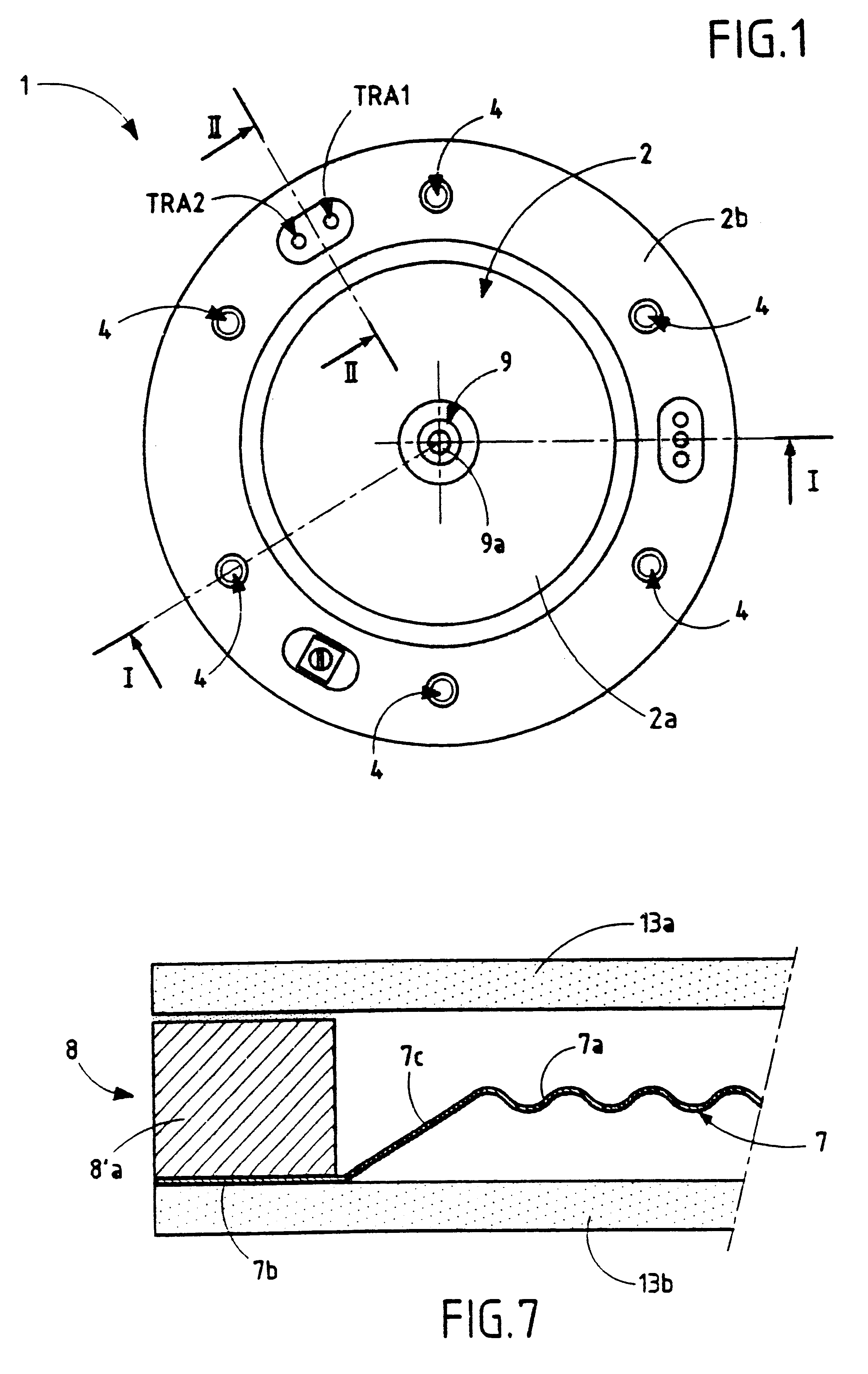
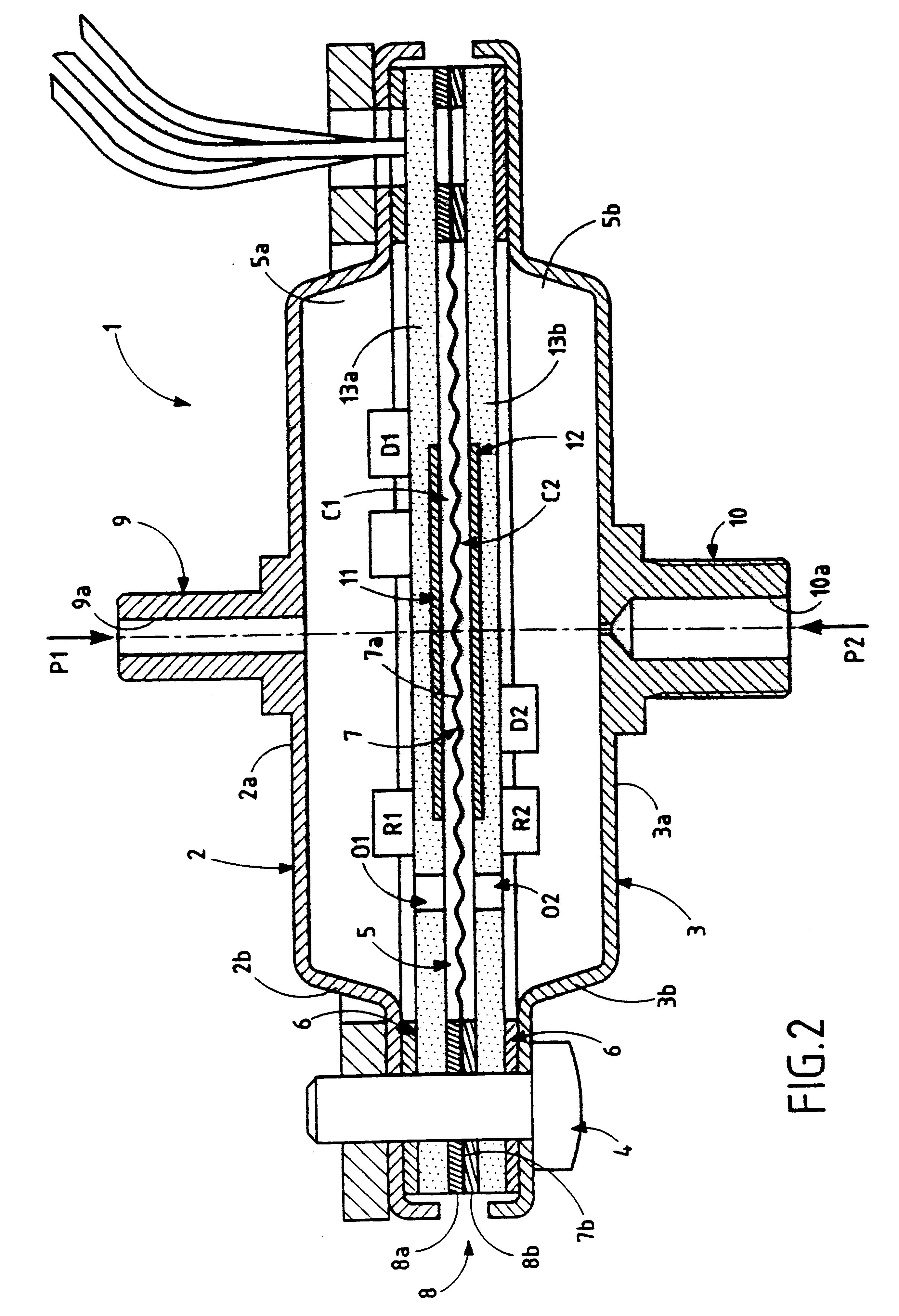
The pressure sensor shown in FIGS. 1 and 2 comprises a housing 1 made up of two similar portions 2 and 3 that are assembled together by screws 4 and that define a closed internal cavity 5 between them, which cavity is preferably cylindrical in shape. As can be seen in FIG. 1, the housing is circular in shape, but it could naturally be of some other shape, e.g. rectangular. A sealing gasket 6, made of elastomer material or of a gasket material that is compatible with the fluid(s) whose pressure is to be measured, is interposed between the two portions 2 and 3 of the housing 1. With reference to FIG. 2, the portions 2 and 3 of the housing are dish shaped in section view, respectively having flat main walls 2a and 3a of predetermined thickness, and peripheral walls 2b and 3b of predetermined height which extend substantially perpendicularly to the main walls 2a and 3a which are associated therewith, and which then extend parallel to said main walls, and terminate with the free ends of ...


PUM


Abstract

A pressure sensor operates on the principle of a differential pair of capacitors having a movable plate that is constituted by the deformable membrane of the sensor. It comprises a measurement circuit for measuring the capacitance of the capacitor, which circuit is incorporated in the housing of the sensor and is made up of first and second double-sided interconnected circuits which are situated on either side of the membrane and which are connected thereto in its peripheral region by connection means. The faces of the circuits which face the membrane serve to mount respective stationary plates of the capacitor, and the faces of the circuits which face away from the membrane comprise respective regions on which components that are sensitive to the displacement of the membrane towards one or other of the fixed plates are mounted, and a region that is insensitive to stray capacitance is also provided on one of the faces that face away from the membrane, for receiving the components forming the remainder of the measurement circuit.

Description

The present invention relates to a differential pressure sensor comprising a housing formed of two portions that are assembled together and that define a closed internal cavity between them, a deformable membrane dividing said internal cavity into two non-communicating chambers which are in communication with sources of fluid under pressure by means of two orifices respectively formed in said portions of the housing, said membrane being made in such a manner as to constitute a plate of first and second variable capacitance capacitors by being associated with two other plates installed in stationary manner in the housing of the sensor on either side of the movable central plate formed by the membrane, and sensor means that is sensitive to the deformation of the membrane as a result of a difference between the pressures existing in the two chambers in order to produce an electrical signal representative of said pressure difference.Presently, sensors of this type are used in particular...

Claims


Application Information

Patent Timeline
IPC IPC(8): G01L9/00G01L9/12G01L13/06
CPCG01L9/0072G01L19/04G01L9/12G01L13/025
Inventor PECHOUX, CHRISTOPHECHEVEUX, JEAN-PIERRE
Owner A THEOBALD
Why Eureka
Try Eureka