Rotator driving device, image forming apparatus using the rotator driving device, and method of driving rotator

a driving device and image forming technology, applied in the direction of mechanical energy handling, electrographic process, instruments, etc., can solve the problems of deteriorating image quality, inconsistency in the print density of a reproduced image, and inability to meet the distances between scanning lines

Inactive Publication Date: 2002-07-16
MINOLTA CO LTD
View PDF18 Cites 40 Cited by
  • Summary
  • Abstract
  • Description
  • Claims
  • Application Information

AI Technical Summary

Benefits of technology

The second object of the present invention is to provide a novel rotator driving device, an image forming apparatus using the rotator driving device, and a novel method of driving a rotator. The rotator driving device of the present invention can respond to the trend toward size reduction, and prevent nonuniformity in rotation or mechanical vibration of a rotator from adversely affecting another rotator so that each rotator can rotate at a constant rotational speed.
With this construction, the rotational drive force of the motor serving as the rotational driving source is transferred to the rotator via the planetary-roller reduction unit. Also, the controller controls the rotational speed of the motor in accordance with the detection result obtained by the speed detector. Consequently, nonuniformity in rotation at high and low frequencies is eliminated, so that the rotational speed of the rotator can be maintained constant. The second object of the present invention can be achieved by a rotator driving device that is provided in an image forming apparatus and that drives first and second rotators provided in the image forming apparatus, the rotator driving device being made up of: a driving unit that includes a motor and supplies a rotational drive force of the motor to the first rotator; a speed detector that detects a rotational speed of the first rotator; a controller that controls a rotational speed of the motor in accordance with a detection result obtained by the speed detector; and a drive branching unit that branches the rotational drive force of the motor and transfers the branched rotational drive force to the second rotator. It should be noted here that "branch" used in the present specification does not mean "separate" or "divide." To be more specific, even after a rotational drive force branches off using the drive branching unit, the branched force is still the same as the original rotational drive force in strength.
By means of this construction, the rotational drive force of the motor is transferred to the first rotator via the speed reducer while the rotational drive force branched by the drive branching unit is transferred to the second rotator. As such, the rotational drive force can be transferred to a plurality of rotators using only one rotational driving source. This leads to space saving, and the image forming apparatus can be manufactured compact. The rotational speed of the motor is controlled in accordance with the detected rotational speed of the first rotator. Thus, if nonuniformity in rotation occurs to the second rotator, the nonuniformity is prevented from being transferred to the first rotator. As a result, the first rotator is always rotationally driven at a constant speed.
With this construction, the rotational drive force can be transferred to a plurality of rotators using only one motor. This leads to space saving and an image forming apparatus including the rotator driving device can be manufactured compact. The drive branching unit is composed of main and slave rotating members, the slave rotating member rotating together with the main rotating member owing to the magnetic action exerted between the main and slave rotating members. By means of this construction of the drive branching unit, nonuniformity in rotation occurring to a rotator can be absorbed more as compared with a case where the rotational drive force branches off using a gear or the like. Consequently, the nonuniformity in rotation can be reliably prevented from adversely affecting another rotator.

Problems solved by technology

If the rotational speed of the drum is unstable, that is, if the drum has nonuniformity in rotation, nonuniformity accordingly occurs in the distances between the scanning lines.
This causes inconsistency in the print density on a reproduced image and so deteriorates the image quality.
It may be caused due to eccentricity of the photosensitive drum and thus occur in a cycle of one rotation of the drum.
Meanwhile, the nonuniform rotation at a high frequency may be caused by improper engagement of gearwheels or a timing belt.
This problem occurs not only to a photosensitive drum provided in an image forming apparatus.
Therefore, these rotator driving devices to be equipped in an apparatus, such as a copier, occupy a large space, thereby making hard to manufacture the apparatus as compact as possible.
In addition, if such low frequency elements occur to one of the idler rollers, the following rotators would be adversely affected by this increased nonuniformity.
Thus, the aim of realizing a driving device that has a high degree of precision cannot be achieved.

Method used


Image

  • Rotator driving device, image forming apparatus using the rotator driving device, and method of driving rotator
  • Rotator driving device, image forming apparatus using the rotator driving device, and method of driving rotator
  • Rotator driving device, image forming apparatus using the rotator driving device, and method of driving rotator

Examples


first embodiment

1. Entire Construction of the Copier

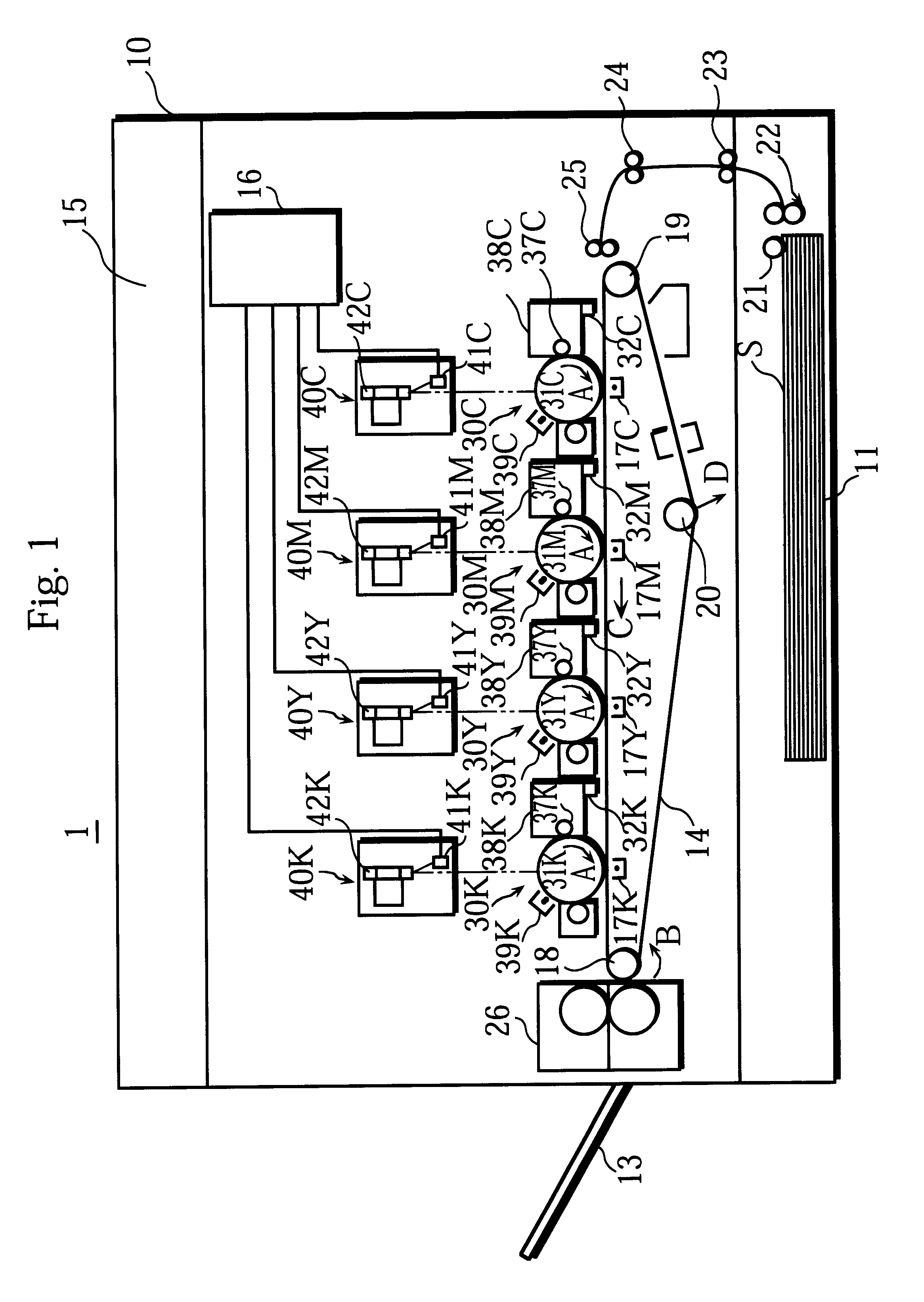
FIG. 1 is a cross-sectional view showing the entire construction of a copier 1 of the present embodiment. The copier 1 includes image forming units 30C, 30M, 30Y, and 30K that are set above a transporting belt 14 along its length. The transporting belt 14 is horizontally set in a lower space of an enclosure 10. Below the transporting belt 14, a paper feeding cassette 11 is set at the lowermost position of the enclosure 10 and can be freely slid in and out of the copier 1. A recording sheet S is taken by a pick-up roller 21 from the paper feeding cassette 11 and then carried to the transporting belt 14 by means of transporting rollers 22 to 25. The transporting belt 14 transports the recording sheet S, and the image forming units 30C to 30K sequentially transfer toner images for reproduction colors, i.e. cyan, magenta, yellow, and black, onto the recording sheet S. The toner images are superimposed on the recording sheet S to form a full-color imag...

second embodiment

In the first embodiment, the photosensitive drums 31C to 31K are rotationally driven using the planetary-roller reduction devices. In the second embodiment, a photosensitive drum and a developing roller are rotationally driven using one driving motor. Note that a copier of the present embodiment is the same as the copier 1 of the first embodiment, except for a rotator driving device used for rotationally driving the photosensitive drum and the developing roller. Therefore, the explanation for the same components of the copiers is omitted in the present embodiment. These same components are assigned the same numerals as in the first embodiment.

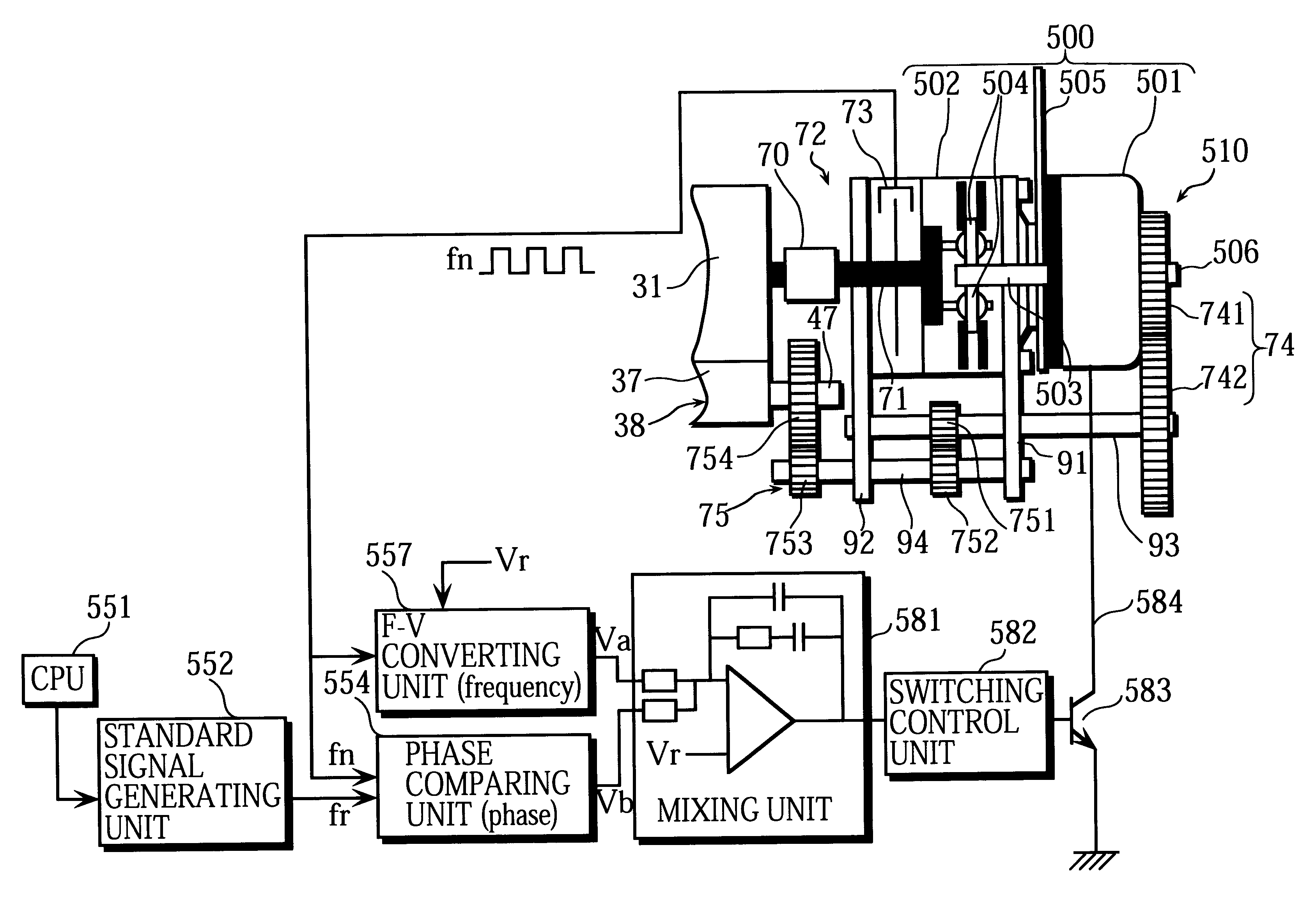
FIG. 7 shows a construction of a driving device 510 for rotationally driving the rotators, i.e. the photosensitive drum and the developing roller of the developing unit. This figure also diagrammatically shows a circuit construction for rotationally driving a driving motor 501. The driving device 510 is provided for each pair of a photosensitiv...

third embodiment

In the second embodiment, the reduction gear mechanism is employed for the branching unit that transfers the rotational force of the driving motor 501 to both the photosensitive drum 31 and the developing roller 37. In the third embodiment, a magnetic linking mechanism using inner and outer magnetic rotators is employed for a branching unit. The magnetic linking mechanism is explained below. Note that a copier of the present embodiment is the same as the copier 1 of the second embodiment, except for the construction of the branching unit. Therefore, the explanation for the same components of the copiers is omitted in the present embodiment.

FIG. 10 shows a construction of a driving device 520 of the present embodiment. The driving device 520 is provided for each pair of a photosensitive drum and a developing unit, meaning that four driving device 520 are provided in the copier of the present embodiment. Therefore, in FIG. 10, the components are assigned numerals without C, M, Y, or K...


PUM


Abstract

Rotational force of a driving motor is transferred to a photosensitive drum via a planetary-roller reduction device, so that the photosensitive drum is rotated. A speed detector set on the shaft of the photosensitive drum detects the rotational speed of the photosensitive drum. In accordance with the detected rotational speed of the photosensitive drum, the rotational speed of the driving motor is adjusted so that the photosensitive drum is rotated at a constant speed.

Description

This application is based on applications No. 11-64051, No. 11-89806, and No. 11-89807 filed in Japan, the contents of which are hereby incorporated by reference.(1) Field of the InventionThe present invention relates to a rotator driving device for rotationally driving a rotator, such as a photosensitive drum provided in a copier, color printer, facsimile, or the like, and also relates to an image forming apparatus using the rotator driving device and a method of rotating such a rotator.(2) Related ArtIn general, a high degree of uniformity is required to rotate a rotator. The reason why the high-degree uniformity is required is given for a case of a photosensitive drum provided as a rotator in, for example, a copier.The photosensitive drum is rotated in one direction, and a laser beam scans the surface of the photosensitive drum in the direction of the axis of rotation (i.e. the main scanning direction) at every scanning cycle. As a result of scanning, an electrostatic latent imag...

Claims


Application Information

Patent Timeline
Patent Type & Authority Patents(United States)
IPC IPC(8): H02K7/10H02K51/00
CPCH02K7/1004H02K51/00
Inventor TSUJIMOTO, TAKAHIROTAKASU, AKIRAFUJIKURA, TERUHIKOMATSUURA, HIDEKIBESSHO, ICHIRO
Owner MINOLTA CO LTD
Why Eureka
Try Eureka