Method for hot-dip galvanizing

a technology of hot-dip galvanizing and hot-dip galvanizing powder, which is applied in the direction of hot-dipping/immersion process, metal material coating process, coating, etc., can solve the problems of degrading quality, increasing the index, and affecting the quality of the produ

Inactive Publication Date: 2002-07-30
JFE STEEL CORP +1
View PDF10 Cites 26 Cited by
  • Summary
  • Abstract
  • Description
  • Claims
  • Application Information

AI Technical Summary

Problems solved by technology

2) In the plating tank, the contained liquid is exchanged before the dross grows to a harmful size.
Accordingly, the apparatus solves several problems such as the investment cost problem accompanied with melt transfer to a distant tank, and the problems of solidification and leak of melt.
With the capacities of plating tank 11 more than 10 m.sup.3, however, the index increases to degrade the quality.
However, in the zones of exceeding W1 / W2=1.0, the index increases to degrade the quality.

Method used


Image

  • Method for hot-dip galvanizing
  • Method for hot-dip galvanizing
  • Method for hot-dip galvanizing

Examples


example 1

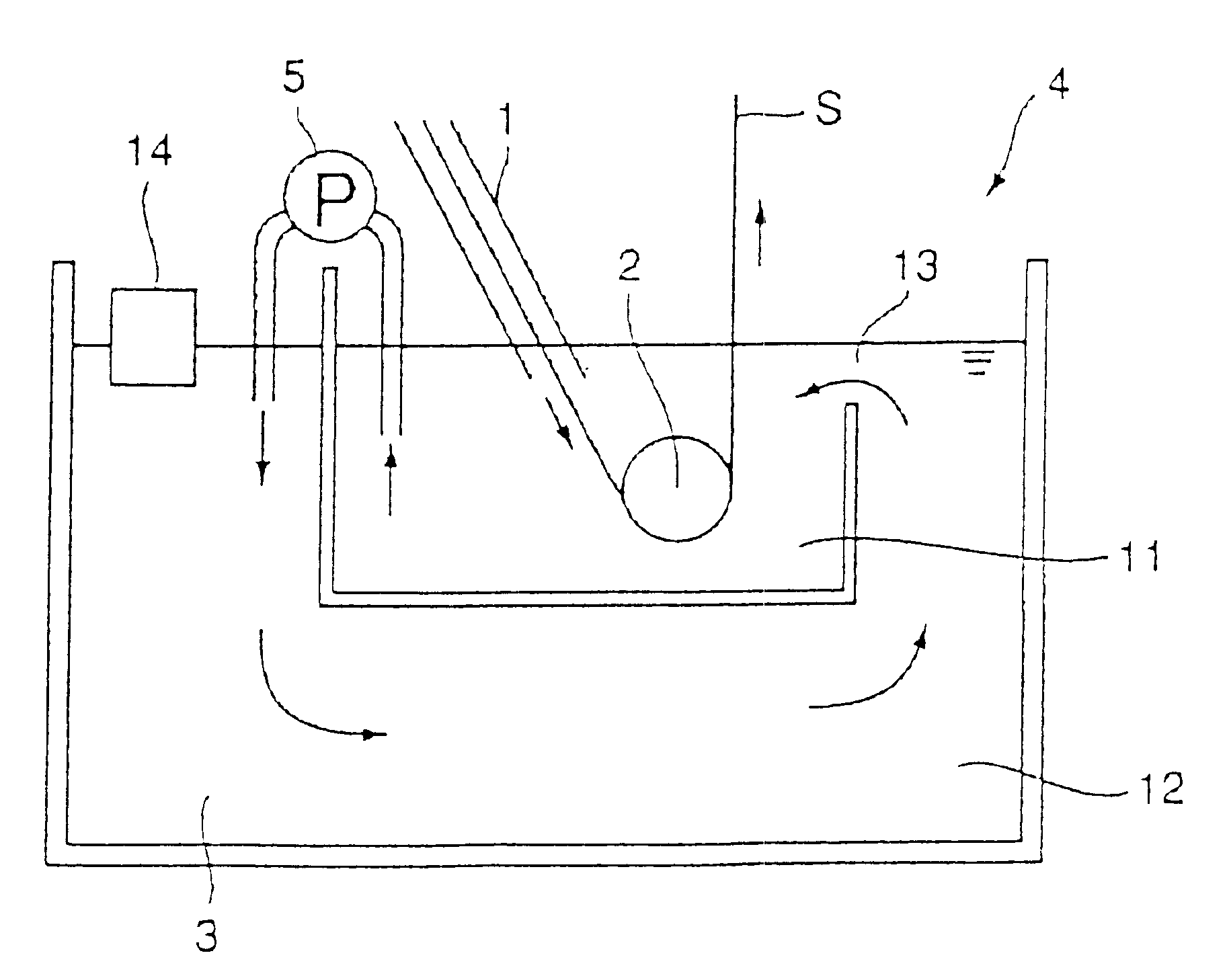
Example 1 used the apparatus shown in FIG. 10. The plating vessel 104 had 2.5 meters in depth. The plating tank 111 had 10 m.sup.3 in capacity, and the dross removing tank 112 had 30 m.sup.3 in capacity. The dross sedimentation speed which raises problem in ordinary hot-dip galvanizing is around 1 meter per hour. Since the depth of the plating vessel 104 was 2.5 meters, the dross removing tank 112 required 2.5 hours or longer retention time. If the circulation flow rate is not more than 12 m.sup.3 / h, the retention time exceeds 2.5 hours, which expects the dross removal effect. On the other hand, if the circulation flow rate becomes below 1 m.sup.3 / h, the dross in the plating tank 111 remains in the plating tank 111 to cause the generation of quality defects. Considering the above-described conditions, the circulation flow rate was selected to 5 m.sup.3 / h.

The apparatus was used to conduct the hot-dip galvanizing to a steel strip. The generation of dross defects on the plated steel...

example 2

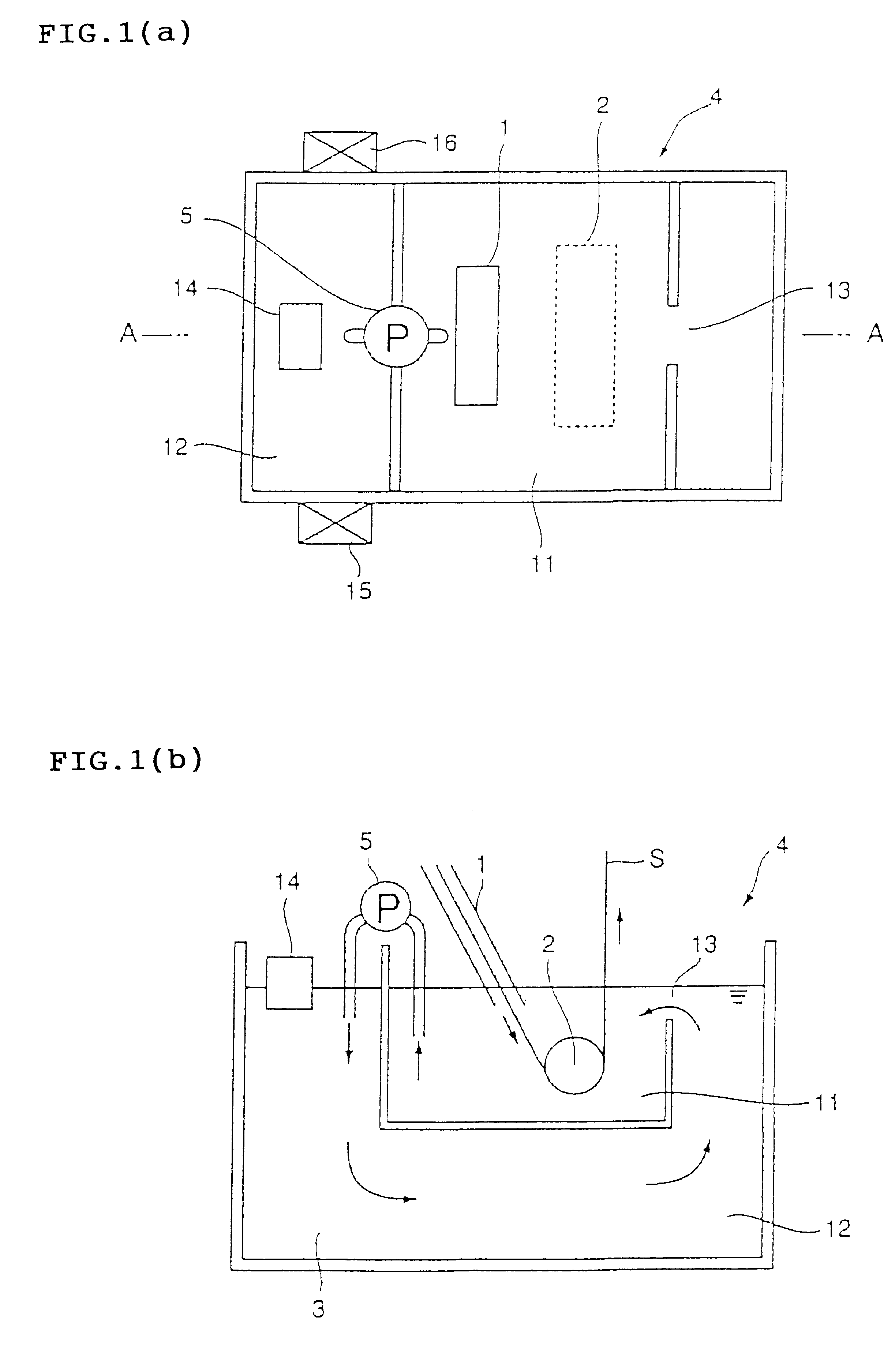
Example 2 used the apparatus shown in FIG. 15. The plating vessel 104 and the plating tank 111 had the same capacities and dimensions as those of Example 1. The hot-dip galvanizing to a steel strip was conducted at a fixed melt circulation flow rate of 5 m.sup.3 / h, which was the same as Example 1. The generation of dross defects on the plated steel strip became zero, compared with around 2% of defect generation in conventional production line. Thus, the problem of dross adherence was completely solved. As a result, the steel strip traveling speed could be increased from conventional level of 100 m / min to 140 m / min.

According to the Best Mode 2, the amount of dross generated during the hot-dip galvanizing on steel strip is reduced, the once-generated dross is prevented from deposition in the plating tank, and the dross is efficiently removed in the dross removing tank located below the plating tank. In addition, since the melt flows with very little flow resistance, there appears ver...

seventh embodiment

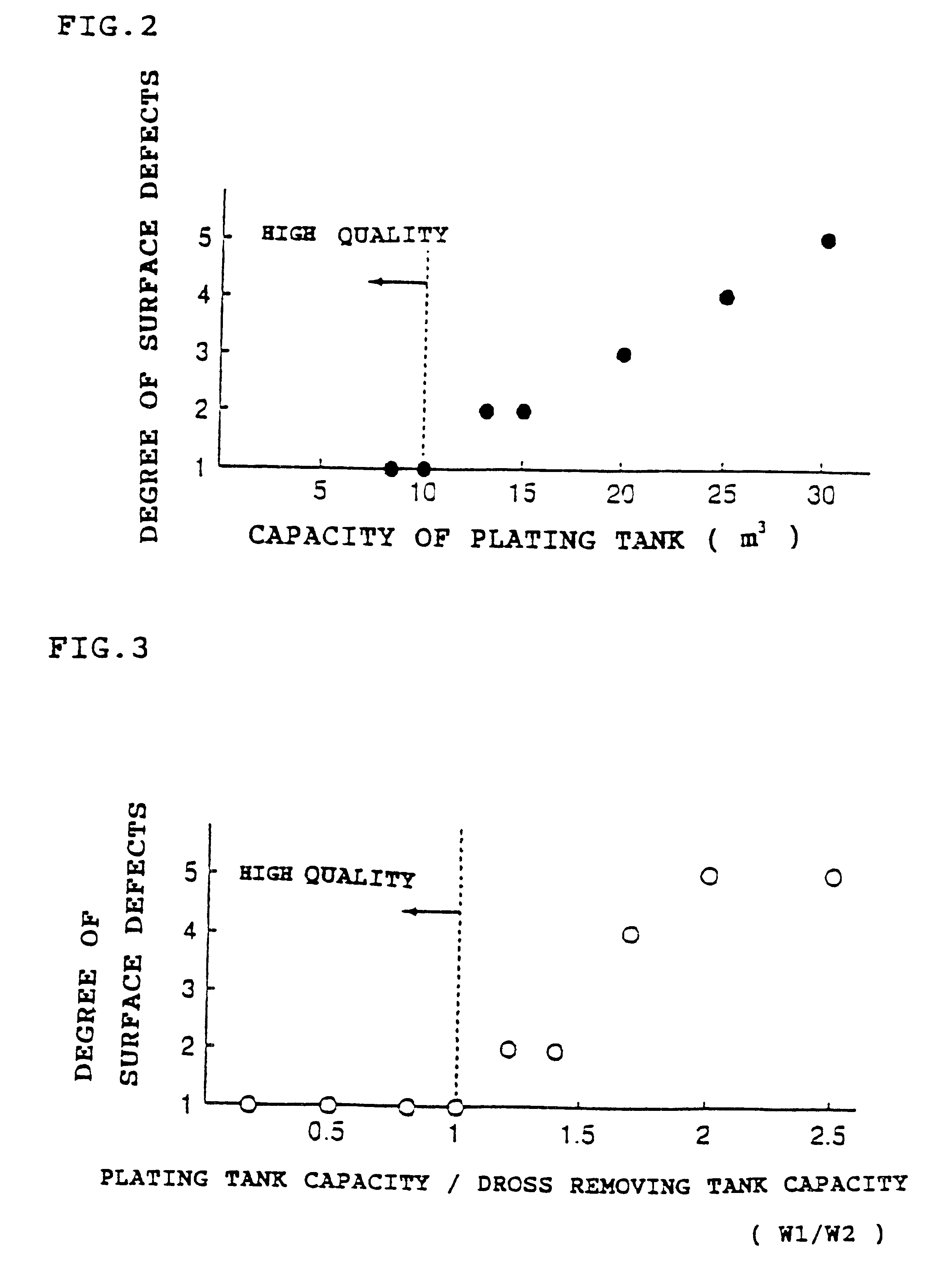
The seventh embodiment is the apparatus for hot-dip galvanizing described in either the fifth embodiment or the sixth embodiment, which apparatus is characterized in that the plating zone has a molten metal bath capacity of W1, and the dross removing zone has a molten metal bath capacity of W2, wherein W1 / W2 is in a range of from 0.2 to 5.


PUM

PropertyMeasurementUnit
hydraulic diameteraaaaaaaaaa
circulation flow rateaaaaaaaaaa
diametersaaaaaaaaaa

Abstract

The method for hot dip galvanizing comprises the steps of: dividing a plating vessel holding a molten metal into a plating tank and a dross removing tank; conducting hot dip galvanizing to a steel strip by immersing thereof in the molten metal bath; then transferring the molten metal bath from the plating tank to the dross removing tank; removing a dross from the molten metal bath in the dross removing tank; and recycling the molten metal bath from the dross removing tank to the plating tank through an opening located on the plating tank. The apparatus for galvanizing comprises a plating tank, a dross removing tank, a means to transfer the molten metal bath from the plating tank to the dross removing tank, and an opening located on the plating tank to recycle the molten metal bath from the dross removing tank to the plating tank.

Description

The present invention relates to a method for hot-dip galvanizing.Generation of surface defects on hot dip galvanized steel strip caused by dross is one of the most serious problems on the hot-dip galvanized steel strip. Dross is an intermetallic compound such as FeZn.sub.7 generated from the reaction between iron and zinc which are eluted from the steel strip in a plating tank holding a zinc-base molten metal, and the dross has spherical equivalent diameters of from 5 to 300 microns. In a stagnant state of the molten metal in the plating tank, the dross deposits on the bottom of the plating tank.However, with a natural convection of the molten metal, generated from the traveling steel strip, from the rotation of immersed rolls in the tank, or from the dissolved zinc-base ingot that supplies the consumed metal brought out along with the steel strip, the molten metal in the plating tank is agitated. As a result, the dross having less difference in specific gravity from the molten met...

Claims


Application Information

Patent Timeline
Patent Type & Authority Patents(United States)
IPC IPC(8): C23C2/00
CPCC23C2/00C23C2/003C23C2/004C23C2/00344C23C2/522C23C2/325C23C2/0036B05C11/10
Inventor ISHII, TOSHIOISHIOKA, MUNEHIRONOMURA, SYU-JIOHSAKI, YASUNORIHATAKEYAMA, SEISHIAKASHI, KENTARONAGAYAMA, RYUJIHADADA, KOZOMIYAKAWA, YOICHIKUNIOKA, KAZUOARAKI, KENJIISHIDA, NOBUYUKIYAMASHITA, KEISHIKUWANA, TERUHISAUESUGI, MOTOI
Owner JFE STEEL CORP
Why Eureka
Try Eureka