Electrode and method of making same

a technology of electric arc welding and electrodes, applied in the direction of welding/cutting media/materials, manufacturing tools, welding apparatus, etc., can solve the problems of inability to filling or alloying agents, inability to resist moisture contamination and physical damage to fluxing, and inability to so as to increase the resistance per length of wire w, accurately control the resistance and welding characteristics of solid wires

Inactive Publication Date: 2002-07-30
LINCOLN GLOBAL INC
View PDF21 Cites 46 Cited by
  • Summary
  • Abstract
  • Description
  • Claims
  • Application Information

AI Technical Summary

Benefits of technology

the wire at that site. This is an advantage of the present invention and allows customized production of a solid welding wire having quantized segments Q.
Referring again to FIG. 1, wire W proceeds from forming wheels 40, 42 and proceeds to guide wheels 50. Two sets of guide wheels are shown in FIG. 1. As can be appreciated, additional or fewer sets of guide wheels can be used. The guide wheels may also be used to control the speed of the wire W to the workpiece WP, smooth the surface of the wire, elongate or otherwise reshape the wire, and/or add components the wire.
FIG. 1A illustrates an alternate method of forming the indentations in wire W. Wire W is unwound from a wire extruder 60 that produces a standard wire W. Forming wheels 40, 42 are positioned adjacent to the outlet of the wire extruder. As wire W pass though the forming wheels, indentations 20 are formed in the wire and define quantized segments Q between the indentations. Other arrangements can be provided for creating the indentations 20, such as laser cutters, end mills, saws, etc. In addition, the wire can be unwound from a roll of wire and fed though one or more forming wheels to create the quantized segments in the wire.
Referring now to FIGS. 2, 2A and 3, a welding wire W constructed in accordance with the present invention is shown. This wire has a series of distinct, quantized segments Q separated by a series of axially spaced indentations 20 inward of cylindrical surface 22 for welding wire W. Quantized segments Q which include indentations 20 can take a variety of shapes. In accordance with the invention, quantized segments Q have a maximum diameter which corresponds to diameter a of wire W. The maximum diameter of the segments determines the cylindrical surface 22 of wire W. The region of the indentations 20 have a diameter b. As illustrated in FIGS. 2, 2A and 3, diameter a is greater than diameter b resulting in the cross-sectional area formed by diameter a being larger than the cross-sectional area formed by diameter b. Quantized segment Q is illustrated in FIG. 2 and has a length equal to length c and d. As shown in FIGS. 2A and 3, indentation 20 has a length d, a width e and a depth f which defines a notch-like region in cylindrical surface 22 of wire W. As can be appreciated, the width e and depth f of indentation 20 can be varied to change the cross-sectional area of the wire in the region of the indentation. The resistance per length of wire W is increased by the indentations 20. The relationship between the length c of segment Q and length d of indentation 20 determines the change, or modification, in the resistance per length of wire W over the resistance per length of a standard wire having the diameter a. Thus, indentations 20 have two overall functions. The indentations separate wire W into a series of quantized segments Q each having essentially the same volume of metal. These indentations also increase the resistance through wire W so that the effective resistance per length of wire W is controlled by the contour, size and configuration of indentations 20. Thus, indentations 20 are used to control the effective resistance of wire W, whereas the quantized segments Q provide controlled droplet transfer of molten metal from wire W during the arc welding process. As can be seen, a variety of dimensions can be provided for segments Q and indentations 20 to accurately control the resistance and welding characteristics of solid wire W. However, wire W still functions as a solid welding wire. The quantizing of segments on

Problems solved by technology

Thus, moisture contamination and physical damage to t

Method used


Image

  • Electrode and method of making same
  • Electrode and method of making same
  • Electrode and method of making same

Examples


Embodiment Construction

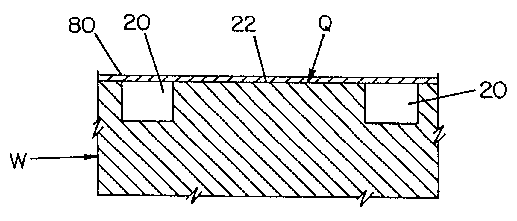
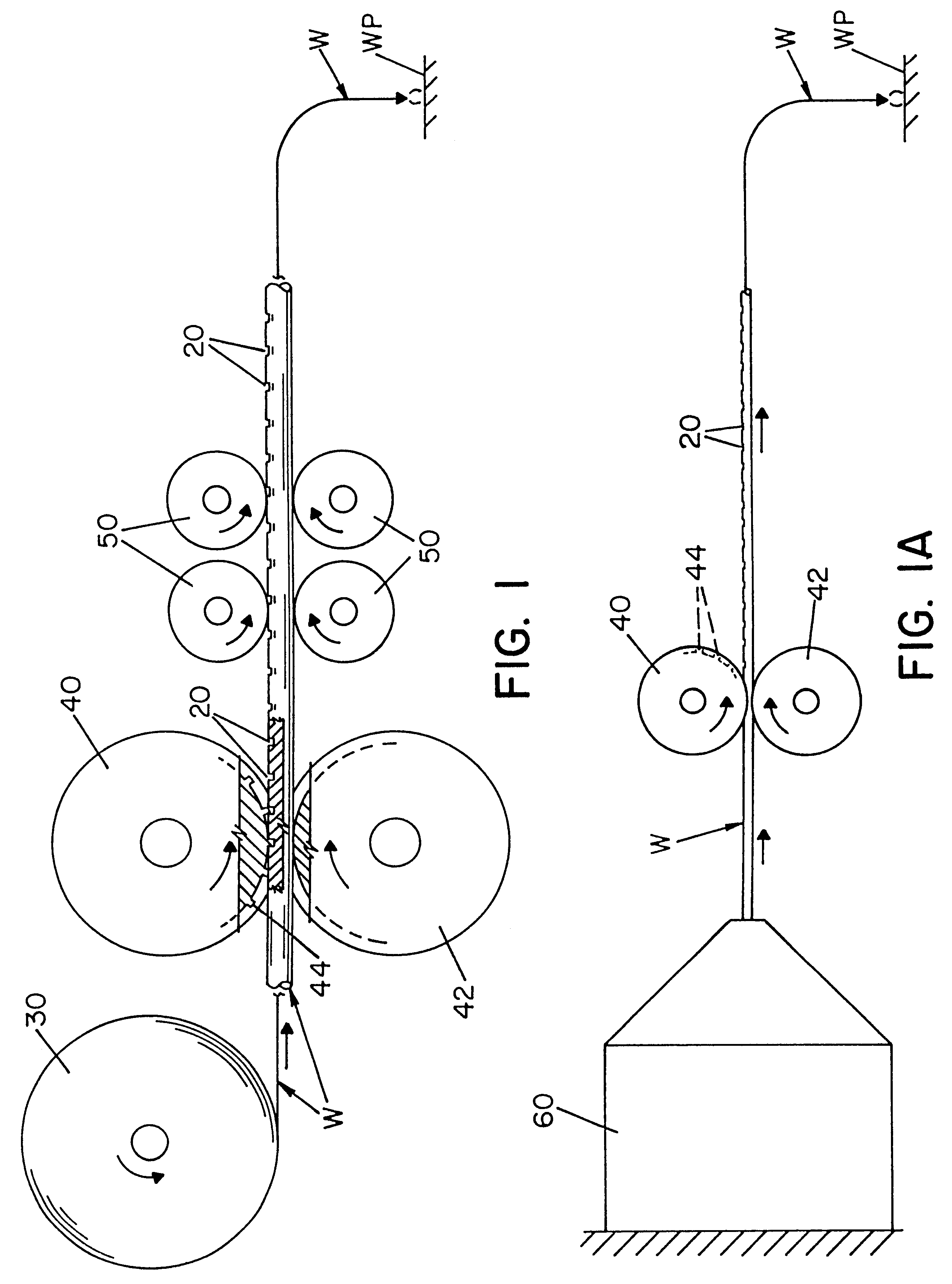
Referring now to the drawings, wherein the showings are for the purpose of illustrating a preferred embodiment of the present invention and not for the purpose of limiting same, FIGS. 1 and 2 illustrate one procedure for forming the grooves or indentations 20 in wire W. FIG. 1 illustrates wire W being unwound from a wire spool 30 that is supplying wire to a welder. As wire W unwinds from spool 30, wire W passes between forming wheels 40, 42 which form indentations 20 in wire W. As can be appreciated, additional or fewer forming wheels can be used. FIG. 1 illustrates that only forming wheel 40 includes have a series of circumferentially spaced teeth 44 on the outer peripheral edge of the forming wheel thereby creating indentations 20 on one side of wire W as shown in FIGS. 2, 2A and 3. As can be appreciated, two or more forming wheels can include teeth to form a wire having indentations on a plurality of sides of the wire. As shown in FIG. 2B and FIG. 4, wire W includes indentations ...


PUM

PropertyMeasurementUnit
Lengthaaaaaaaaaa
Electrical conductivityaaaaaaaaaa
Diameteraaaaaaaaaa

Abstract

A welding wire for use in electric arc welding and method of making same, wherein the wire has an effective outer diameter and comprises a length of solid metal formed into a series of distinct segments each having a selected volume and having an indented and non-indented region with the cross sectional area of the solid metal at said non-indented region being greater than the cross sectional area of the solid metal at the indented region.

Description

The present invention relates to the art of electric arc welding of the type where a welding wire is directed toward a workpiece and an electrical current is passed through the welding wire to the workpiece to create an arc welding process melting the end of the advancing wire and depositing the melted metal onto the workpiece and more particularly to an improved welding wire for use in this arc welding process and the method of making this improved welding wire.INCORPORATION BY REFERENCEU.S. patent application Ser. No. 09 / 024,392 filed Feb. 17, 1998 is incorporated by reference herein to provide information on solid metal welding wire which has distinct quantized segments that facilitate superior droplet transfer.BACKGROUND OF INVENTIONElectric arc welding of the type to which the present invention is directed involves the use of a welding wire normally stored upon a spool or reel, which wire is fed from the supply reel toward a workpiece through a tubular connector so that current...

Claims


Application Information

Patent Timeline
IPC IPC(8): B23K35/02B23K9/24
CPCB23K9/24B23K35/0261
Inventor BLANKENSHIP, GEORGE D.ENYEDY, EDWARD A.
Owner LINCOLN GLOBAL INC
Why Eureka
Try Eureka