Switch-mode power supplies

a power supply and switch-mode technology, applied in the field of switch-mode power supplies, can solve the problems of high loss in the mosfet switch and in the snubber network, 5 watts of heat dissipation in the rectifier, and may not be easily met, and achieve the requirements of high efficiency, small size and low cos

Inactive Publication Date: 2002-08-06
NGUYEN TRANH TO
View PDF5 Cites 33 Cited by
  • Summary
  • Abstract
  • Description
  • Claims
  • Application Information

AI Technical Summary

Problems solved by technology

Conventional approaches to SMPS, such as the forward converter taught in U.S. Pat. No. 4,870,555, or the push-pull converter taught in U.S. Pat. No. 5,140,509, or a flyback SMPS result in high losses in the MOSFET switches, and in the snubber networks, even in the so-called "loss...

Method used


Image

  • Switch-mode power supplies
  • Switch-mode power supplies
  • Switch-mode power supplies

Examples


Embodiment Construction

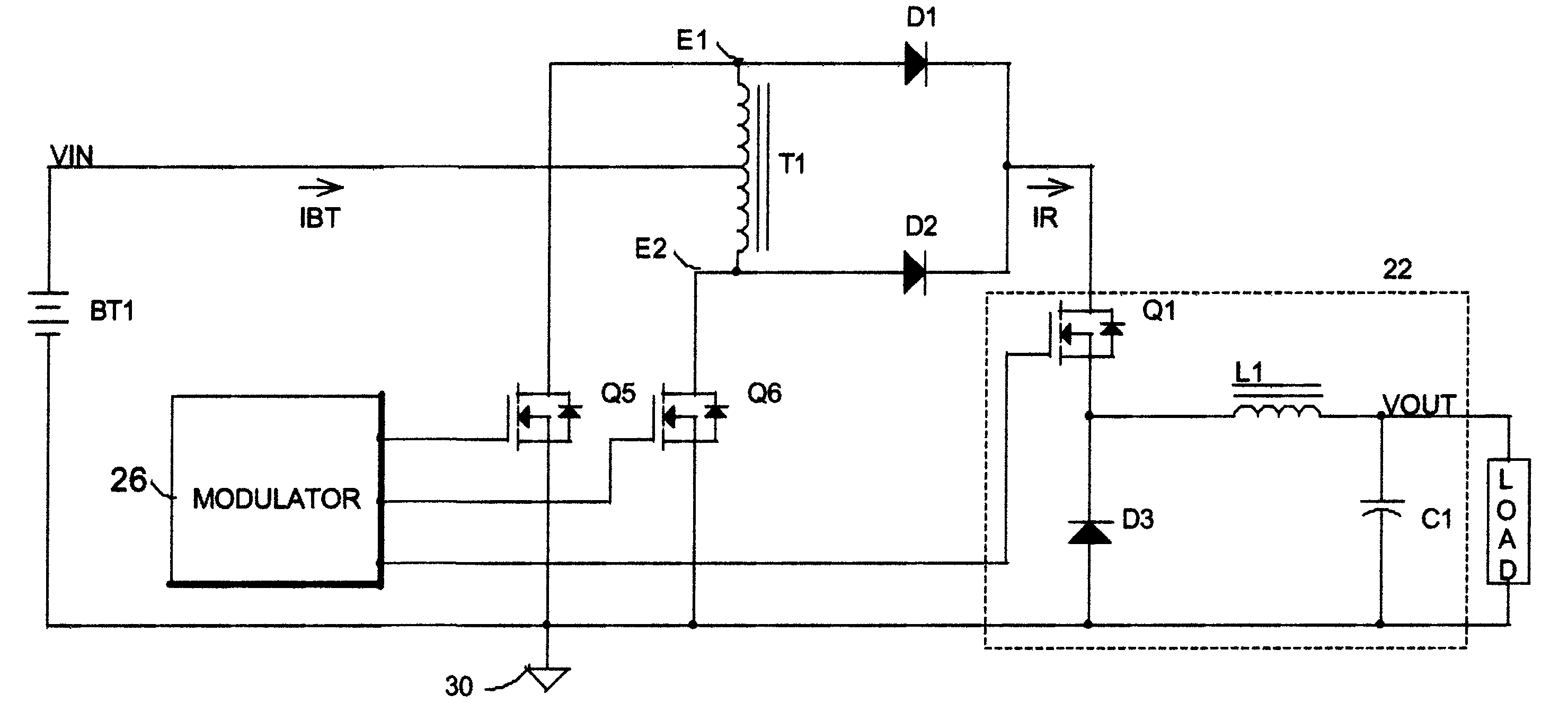
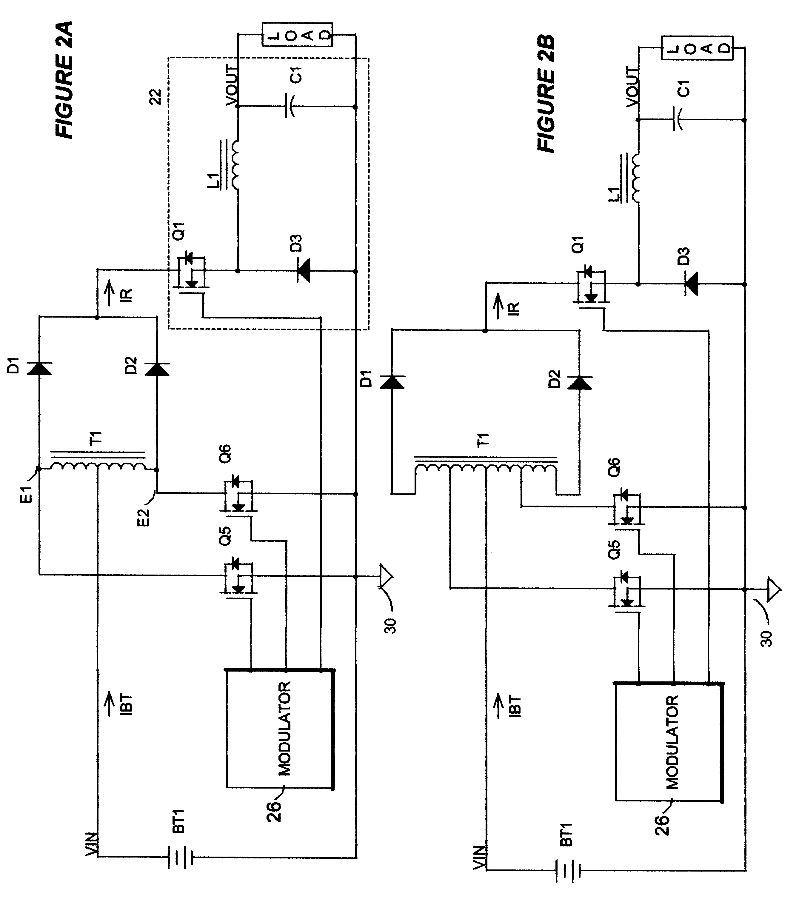
The invented arrangement in a first embodiment, FIG. 2A, comprises a center-tapped transformer T1 operated in push-pull mode. The transformer T1 is driven by a pair of push-pull switches Q5 and Q6, which are preferably MOSFETs, but which can be any other sort of electronic switch known to those skilled in the art, such as a bipolar transistor, an IGBT. However its similarity to a push-pull SMPS stops there. The two end taps E1 and E2 of the center-tapped transformer T1 now are connected to rectifiers D1 and D2 driving a buck converter 22, which is driven synchronously by the same modulator 26 which drives the push-pull switches Q5-Q6. The conventional buck converter 22 comprises a switch Q1, a rectifier D3, and a current smoothing L1, and optionally a capacitor C1. The modulator 26 can be a pulse-width modulator (PWM), a pulse-frequency modulator (PFM), a hysteretic modulator etc . . . . This invented circuit arrangement has a voltage gain of 2 times the duty ratio D of the push-pul...


PUM


Abstract

A family of switch-mode power supplies with low current stresses on switches and capable of producing an output voltage higher than the input voltage, incorporating a multiple-tap transformer driven by at least one ground-referenced switch. When the transformer is center-tapped, it is driven by two ground-referenced switches. The current stress in each switch is equal to the difference between the source current and the load current. The converters can operate in zero current switching and zero voltage switching. Integrated magnetics can be used to reduce further component count.

Description

The present invention relates generally to switch-mode power supplies, and specifically to switch-mode power supplies operating from low voltages.BACKGROUND OF INVENTIONPower converters or power supplies are well known subjects to electronics engineers. In automotive applications where the vehicle chassis forms a ground reference, power supplies for electronics must operate from battery voltage which can get as low as 7 volts when the ambient air temperature is below freezing, even down to 3.5V when a starter is activated. Most modem electronic circuits operate on standard voltages such as +12V, +5V, and -12V. Therefore a buck-type, as depicted in FIG. 1A, or boost-type, as depicted in FIG. 1B, switch-mode power supply (SMPS) cannot be used alone in automotive applications. A flyback SMPS, as depicted in FIG. 1C, can be used, only to supply relative low power levels. As a result of low minimum battery voltages, the current level that a SMPS has to deal with can be very high, in the ...

Claims


Application Information

Patent Timeline
IPC IPC(8): H02M3/04H02M3/158
CPCH02M3/158H02M2001/0064H02M2001/007H02M1/0064H02M1/007
Inventor NGUYEN, TRANH TO
Owner NGUYEN TRANH TO
Why Eureka
Try Eureka