Power converters having capacitor resonant with transformer leakage inductance

a technology of capacitor resonant and transformer, which is applied in the direction of electric variable regulation, process and machine control, instruments, etc., can solve the problems of high operating frequency, large increase in body diode conduction loss, reverse recovery loss and switching loss,

Inactive Publication Date: 2007-03-27
VIRGINIA TECH INTPROP INC
View PDF7 Cites 36 Cited by
  • Summary
  • Abstract
  • Description
  • Claims
  • Application Information

AI Technical Summary

Problems solved by technology

However, high operating frequencies greatly increase body diode conduction losses, reverse recovery losses and switching losses.
Another problem with high frequency operation is switching noise.
The reverse-recovery charge of the switches creates high voltage spikes.
High voltage-rating switches typically have high ON-state resistance (Rds(on)) and therefore higher conduction loss.
During dead times 14, the body diodes of secondary switches S1 S2 conduct current pulses 16, resulting in substantial energy loss and reverse recovery loss.
The body diode conduction loss and reverse recovery loss increase as operating frequency increases, and result in lower power conversion efficiency.

Method used


Image

  • Power converters having capacitor resonant with transformer leakage inductance
  • Power converters having capacitor resonant with transformer leakage inductance
  • Power converters having capacitor resonant with transformer leakage inductance

Examples


Embodiment Construction

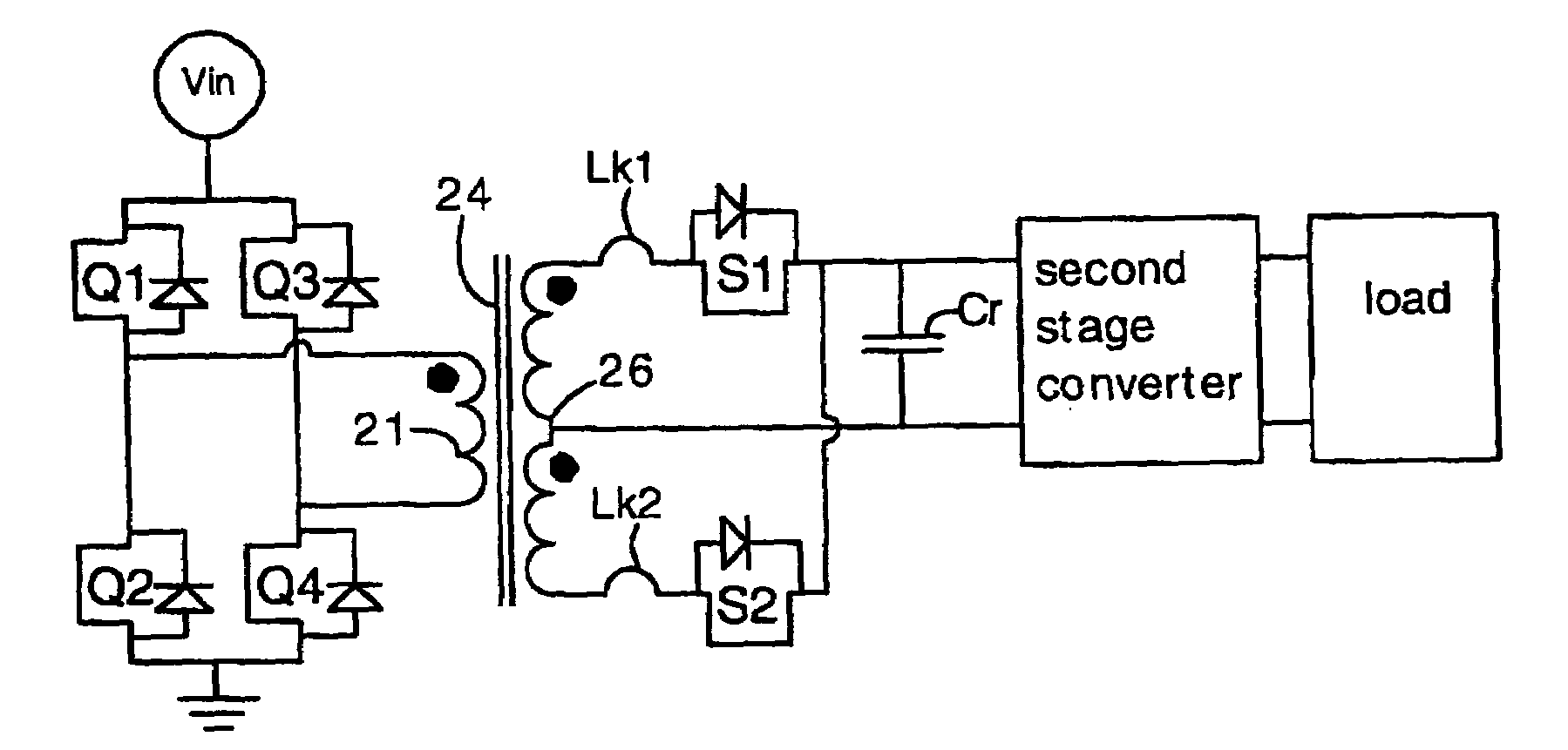
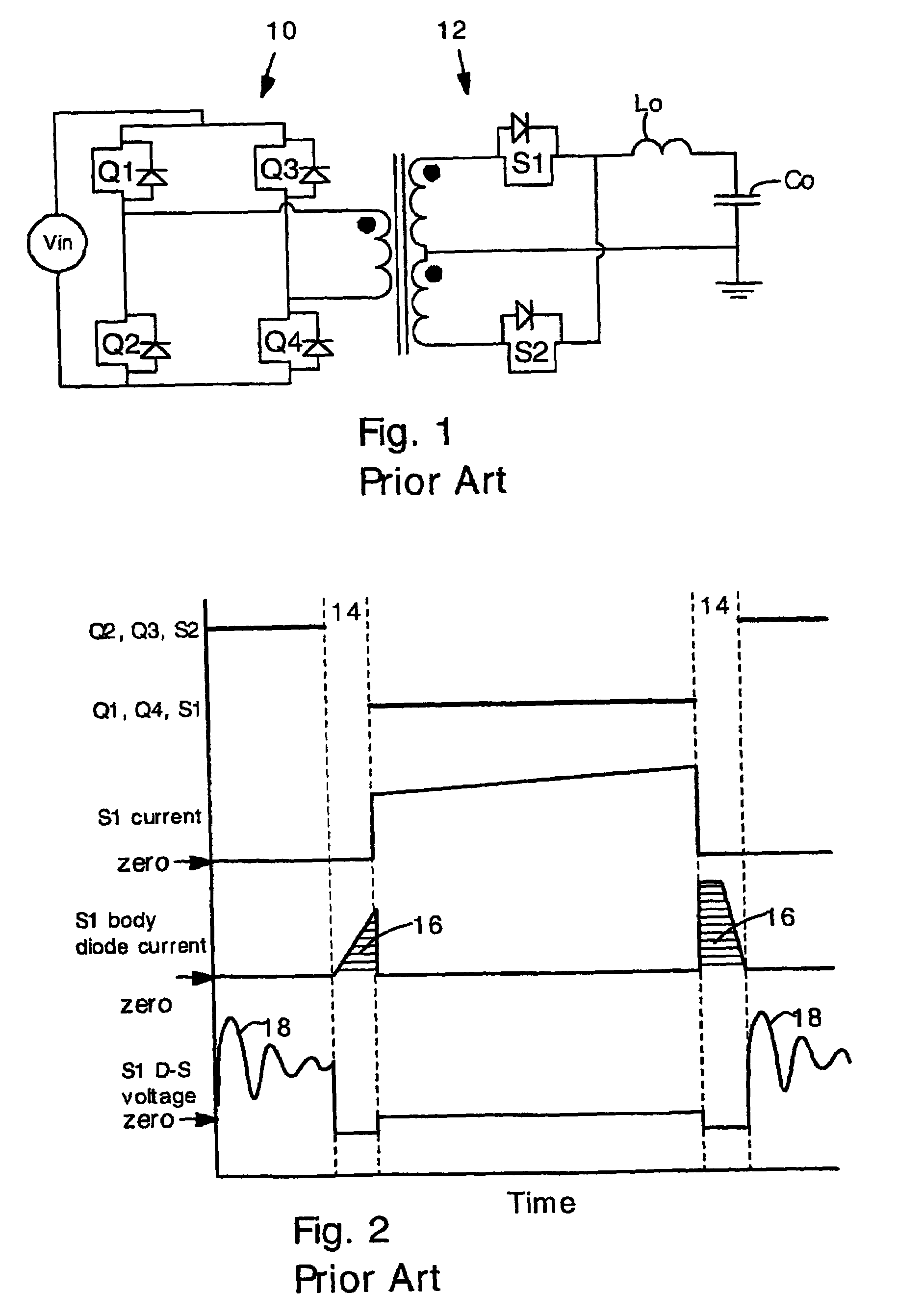
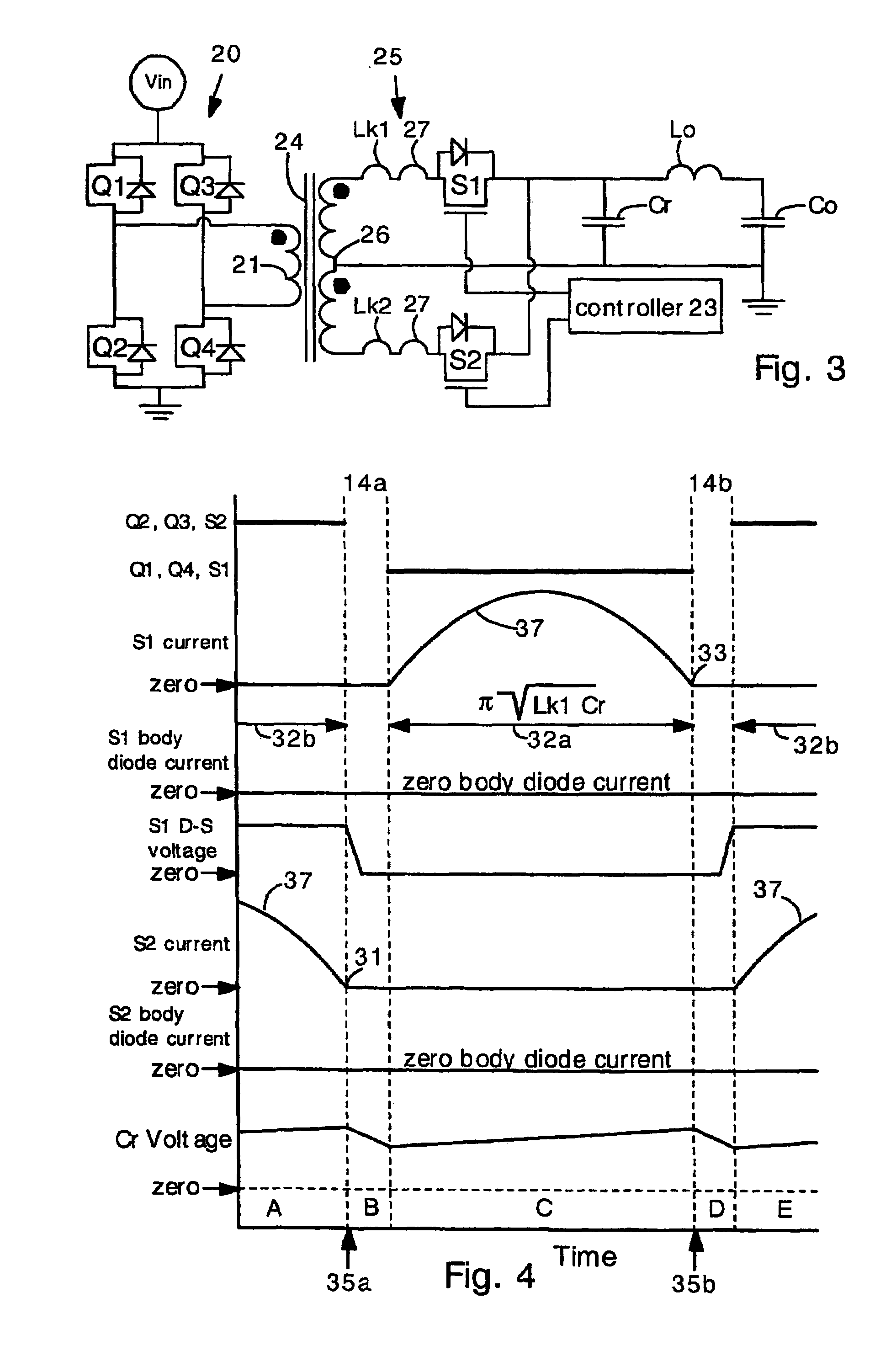
[0025]The present invention provides a power converter with reduced body diode conduction loss, reduced reverse recovery loss and reduced voltage spikes. Additionally, the present power converters can also have zero-voltage switching (ZVS) operation and reduced turn-off loss. The present power converters can operate at high frequencies (e.g. 1–2 Mhz), and can therefore have small passive components and high power density. The present power converters provide exceptionally high efficiency.

[0026]In the present invention, the secondary circuit comprises a resonant capacitor. The resonant capacitor resonates with leakage inductance of the transformer. The resonant frequency is selected such that ½ of a LC resonant period is the same duration as an ON time of a secondary switch. The resonance between the resonant capacitor and leakage inductance produces a sinusoidal (or nearly sinusoidal) current pulse through the secondary switches. The sinusoidal pulse shape results in greatly reduced...


PUM


Abstract

Power converters having reduced body diode conduction loss, reduced reverse recovery loss and lower switching noise, among other benefits, have a resonant capacitor Cr connected across an unfiltered output. The resonant capacitor Cr resonates with the leakage inductance Lk of the transformer. The resonant capacitor and leakage inductance are selected such that ½ a LC resonance period is equal to an ON time of each secondary switch S1 S2. The resonance provides zero current switching for secondary switches S1 S2, eliminates zero body diode conduction during dead times, and eliminates reverse recovery losses in the secondary switches. The present invention is applicable to many different circuit topologies such as full bridge, active clamp forward, push-pull forward, and center-tap secondary. The present converters provide high energy conversion efficiency and high frequency operation.

Description

FIELD OF THE INVENTION[0001]The present invention generally relates to synchronous power converters. More particularly, the invention relates to a family of power converters having no requirement for an output inductor, and having a resonant output capacitor. The present converters have a high power conversion efficiency.BACKGROUND OF THE INVENTION[0002]Synchronous power converters are widely used in computer and telecommunication electronics. Such power converters typically convert 48 volt bus power to lower voltages (e.g. 12V, 5V and 1.2V) needed for operating microprocessors and the like.[0003]Modern electronics are decreasing in size and typically require increased operating current at lower voltages. As a result, power converters must provide more power while occupying less circuit board space. In order to meet these requirements, power converters must operate at higher frequencies. A high operating frequency allows for smaller passive components. However, high operating freque...

Claims


Application Information

Patent Timeline
Patent Type & Authority Patents(United States)
IPC IPC(8): H02M3/335
CPCH02M3/33569H02M3/33592Y02B70/1475Y02B70/1433Y02B70/10H02M1/0058H02M3/33573H02M3/33571H02M3/01
Inventor REN, YUANCHENGLEE, FRED C.XU, MING
Owner VIRGINIA TECH INTPROP INC
Why Eureka
Try Eureka