Heat sensitive type printer

a type printer and heat-sensitive technology, applied in the field of heat-sensitive type printers, can solve the problems of difficult to uniformly cool light-emitting surfaces, and uneven surface temperature of light-emitting surfaces

Inactive Publication Date: 2002-08-06
FUJIFILM HLDG CORP +1
View PDF2 Cites 7 Cited by
  • Summary
  • Abstract
  • Description
  • Claims
  • Application Information

AI Technical Summary

Benefits of technology

Since the air that cools the thermal head or the light emission surface of the surface luminous device also cools the other of the thermal head and the light emission surface, both of the thermal head and the light emission surface the single cooling device are cooled with efficiency. Since the air guide guides the cooling air to flow along the light emission surface in the lengthwise direction of the paper transport path, the cooling air is prevented from blowing the heat sensitive recording paper, and thus from influencing the temperature and the moisture of the recording paper.

Problems solved by technology

If the luminous intensity of the optical fixing device varies during the optical fixation, the coloring layer is not uniformly fixed.
Concerning the surface luminous device, however, it has been difficult to cool the light emission surface uniformly just by blowing cold air from lateral sides of the light emission surface.
Since the light emitting surface of the planer ultraviolet light emitting device extends across the width of the heat sensitive recording paper, that is, in a transverse direction to the paper transporting direction, the method of sending cooling air from the lateral side results unevenness in surface temperature of the light emission surface, and thus unevenness in the optical fixation, particularly in the widthwise direction of the heat sensitive recording paper.
Using a lot of cooling fans for uniform cooling results in rising the cost and the size of the heat sensitive type printer.
Moreover, the cold air blowing the light emission surface can cool the heat sensitive recording paper and cause unexpected temperature variations of the heat sensitive recording paper, which results improper coloring densities.

Method used


Image

  • Heat sensitive type printer
  • Heat sensitive type printer
  • Heat sensitive type printer

Examples


Embodiment Construction

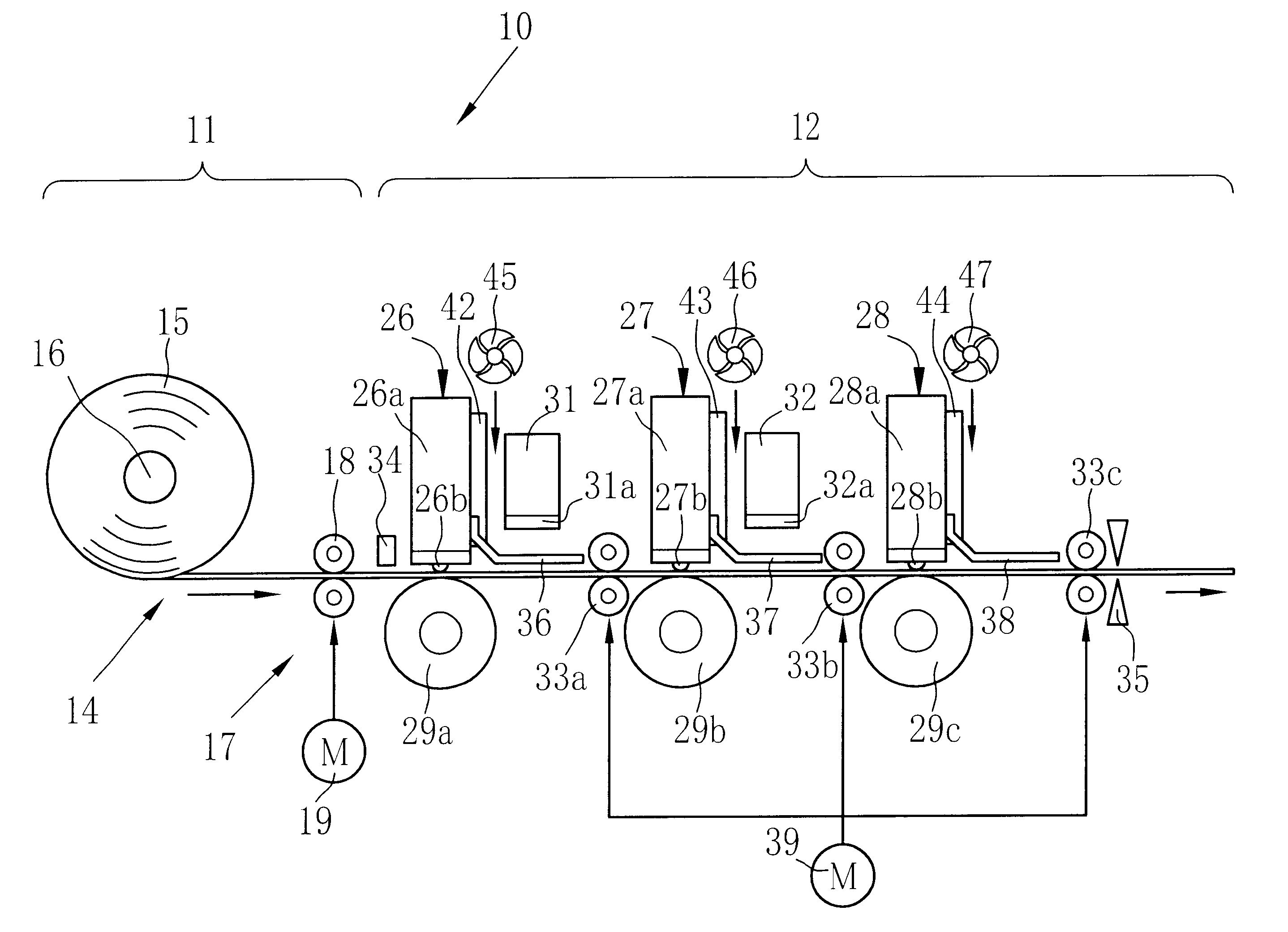
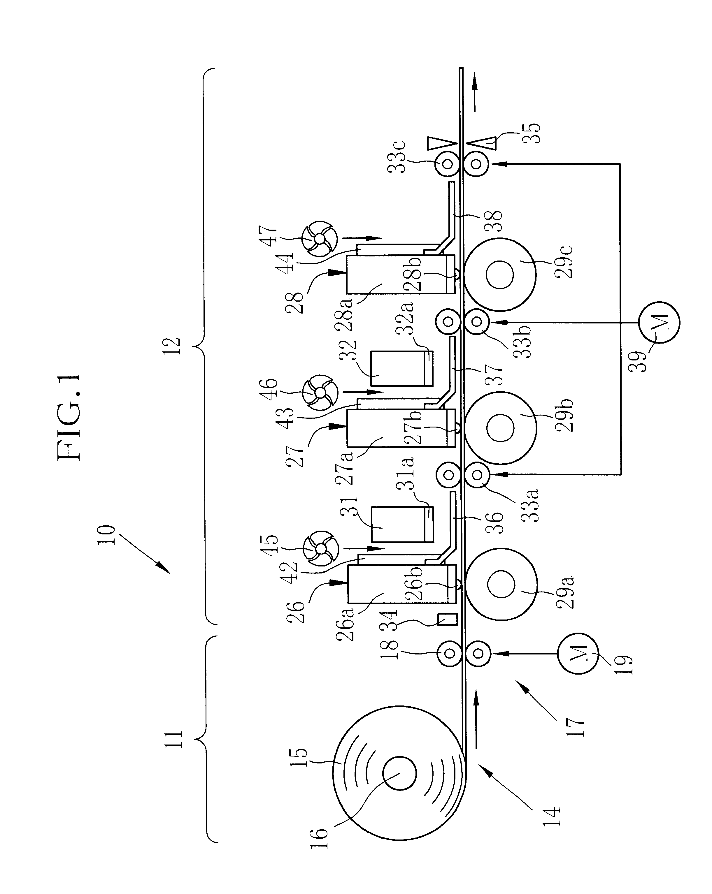
A three-head one-pass type heat sensitive color printer 10 shown in FIG. 1 consists of a paper supply section 11 and an image recording section 12. In the paper supply section 11, a roll 15 of heat sensitive color recording paper 14 is rotatably held on a rotary shaft 16. A paper supply mechanism 17 consists of paper supply rollers 18 and a pulse motor 19 for driving the paper supply roller 18. The paper supply rollers 18 nip and pull out the heat sensitive recording paper 14 from the roll 15, to feed it to the image recording section 12. Rotational movement of the pulse motor 19 is controlled by a not-shown system controller.

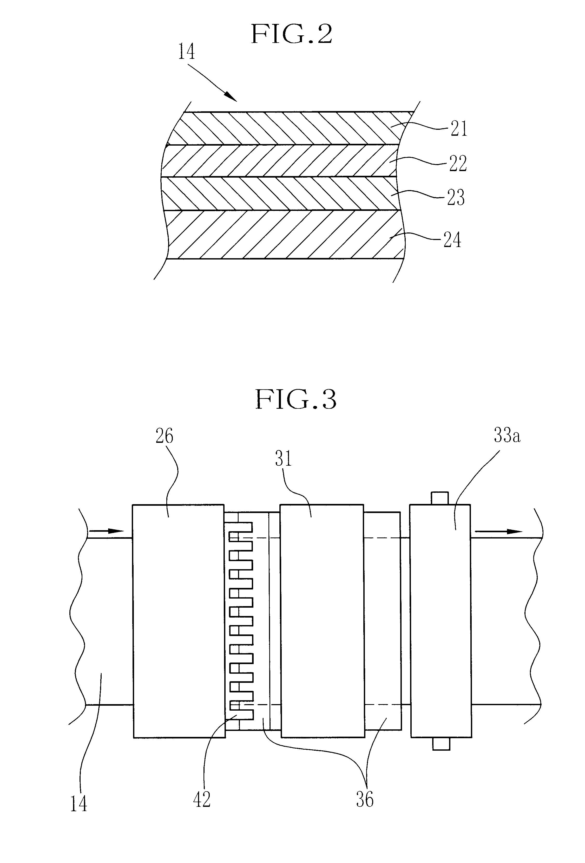
As shown in FIG. 2, the heat sensitive recording paper 14 has a heat sensitive yellow coloring layer 21, a heat sensitive magenta coloring layer 22 and a heat sensitive cyan coloring layer 23 formed atop another on a base material 24, in this order from an obverse side opposite to the base material 24. The topmost yellow coloring layer 21 has the highest heat s...


PUM


Abstract

There is disclosed a heat sensitive type printer wherein glass plates (36, 37, 38) are secured at one ends to thermal heads (26, 27, 28), and extend substantially in parallel to a paper transport path of a heat sensitive color recording paper (14). Surface luminous devices (31, 32) for fixing coloring layers of the recording paper optically are disposed adjacent to heat sinks of the thermal heads with their light emission surfaces facing the paper transport path through the glass plates. Cooling fans send air into between the heat sinks and the surface luminous devices, to cool the heat sinks. Thereafter, the air guide guides the air to flow along a gap between the light emission surface and the glass plate, thereby to cool the light emission surface.

Description

1. Field of the InventionThe present invention relates to a heat sensitive type printer, and more particularly to a cooling fan of the heat sensitive type printer, that is provided for cooling a thermal head and a surface luminous device for optical fixing.2. Background ArtsThe heat sensitive type printer records an image on a heat sensitive recording paper that develops colors when it is heated, by heating the heat sensitive recording paper through a thermal head while moving the heat sensitive recording paper relative to the thermal head. Heat sensitive type color printers for recording full-color images use a heat sensitive color recording paper that has a heat sensitive cyan coloring layer, a heat sensitive magenta coloring layer and a heat sensitive yellow coloring layer which are formed atop another sequentially from a base material. These heat sensitive coloring layers have different heat sensitivities so that these coloring layers may develop colors sequentially from the mos...

Claims


Application Information

Patent Timeline
Patent Type & Authority Patents(United States)
IPC IPC(8): B41J2/32B41J2/325
CPCB41J2/32B41J2202/32B41J2202/34
Inventor TAKI, TOMOKOKOKUBO, HIDEYUKI
Owner FUJIFILM HLDG CORP
Why Eureka
Try Eureka