Determination of center of focus by diffraction signature analysis

a diffraction signature and center of focus technology, applied in the field of diffraction signature analysis, can solve the problems of difficult automation, relatively slow operation, and expensive process

Inactive Publication Date: 2002-08-06
ONTO INNOVATION INC
View PDF19 Cites 95 Cited by
  • Summary
  • Abstract
  • Description
  • Claims
  • Application Information

AI Technical Summary

Benefits of technology

A primary advantage of the present invention is that it permits measuring parameters relating to a lithography device without the use of optical, SEM or similar microscopy metrology tools.
Another advantage of the present invention is that it permits use of a series of different focus diffraction gratings on a conventional wafer made by means of a stepper, including conventional photoresist lithography means, to determine center of focus utilizing determination of diffraction signatures, and the differences therebetween, for the diffraction gratings.
Another advantage of the present invention is that it provides a method and device that permits obtaining results, including center of focus, in a lithography device, such as a stepper, in a shorter period of time and at lower cost than conventional and known methods.

Problems solved by technology

However, while SEM metrology can resolve features on the order of 0.1 microns, the process is costly, requires a high vacuum chamber, is relatively slow in operation and is difficult to automate.
Optical microscopes can be employed, but do not have the required resolving power for sub-micron structures.
However, these methods, while increasing resolution because of the nature of the targets, still require use of SEM, optical microscopes or similar direct measurement devices.
However, this method requires significant time and computer resources to generate the theoretical model.

Method used


Image

  • Determination of center of focus by diffraction signature analysis
  • Determination of center of focus by diffraction signature analysis
  • Determination of center of focus by diffraction signature analysis

Examples


Embodiment Construction

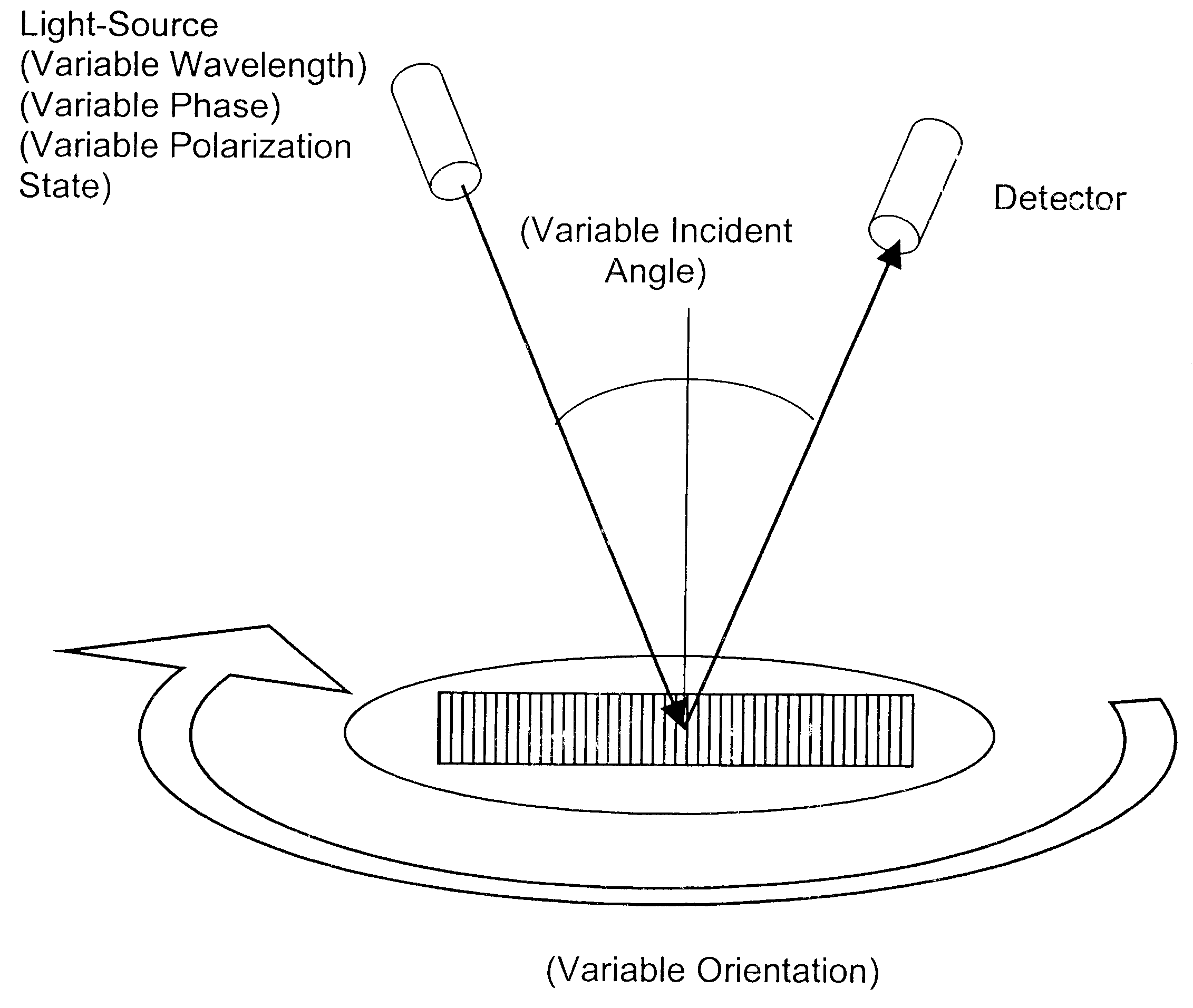
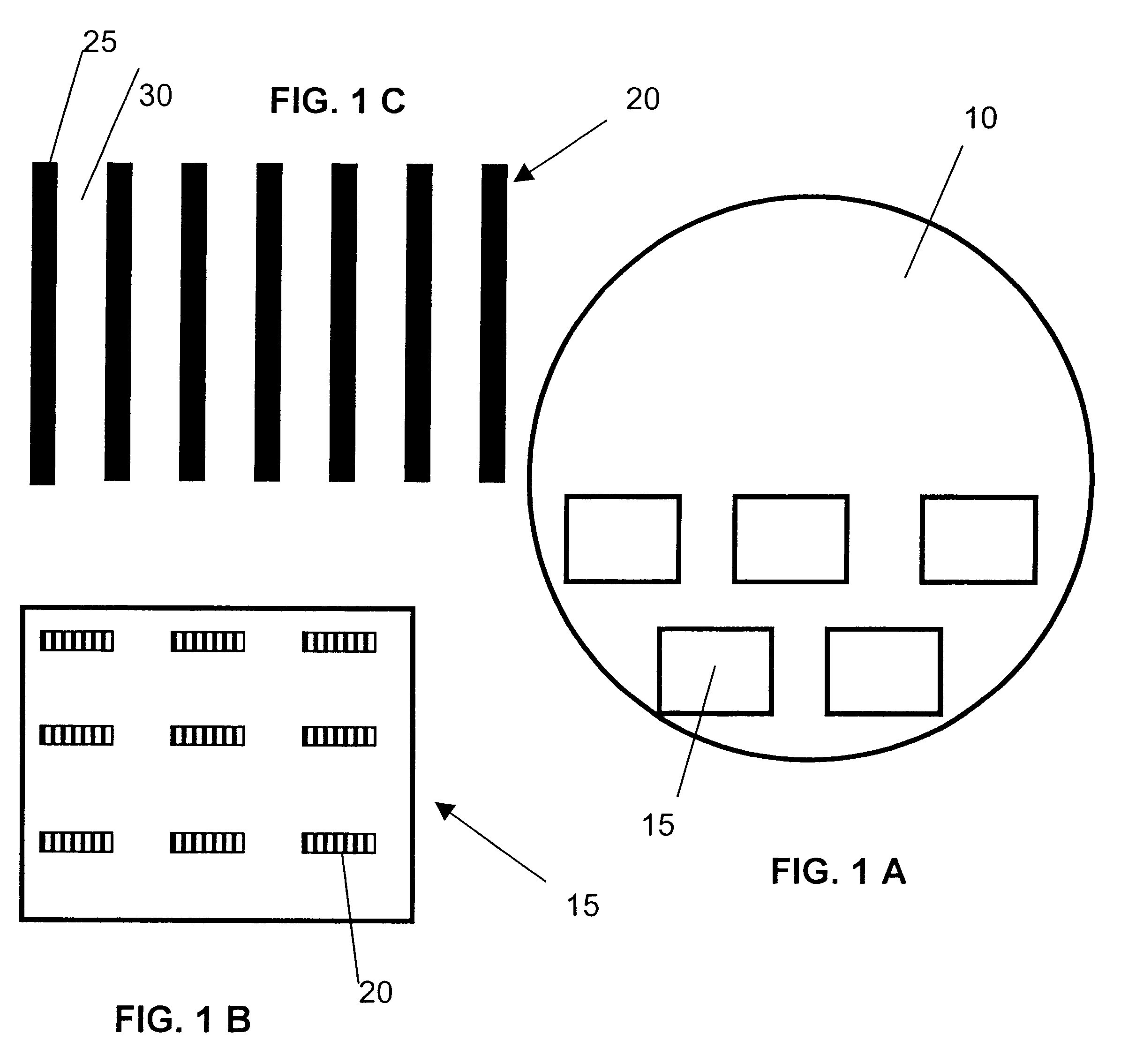
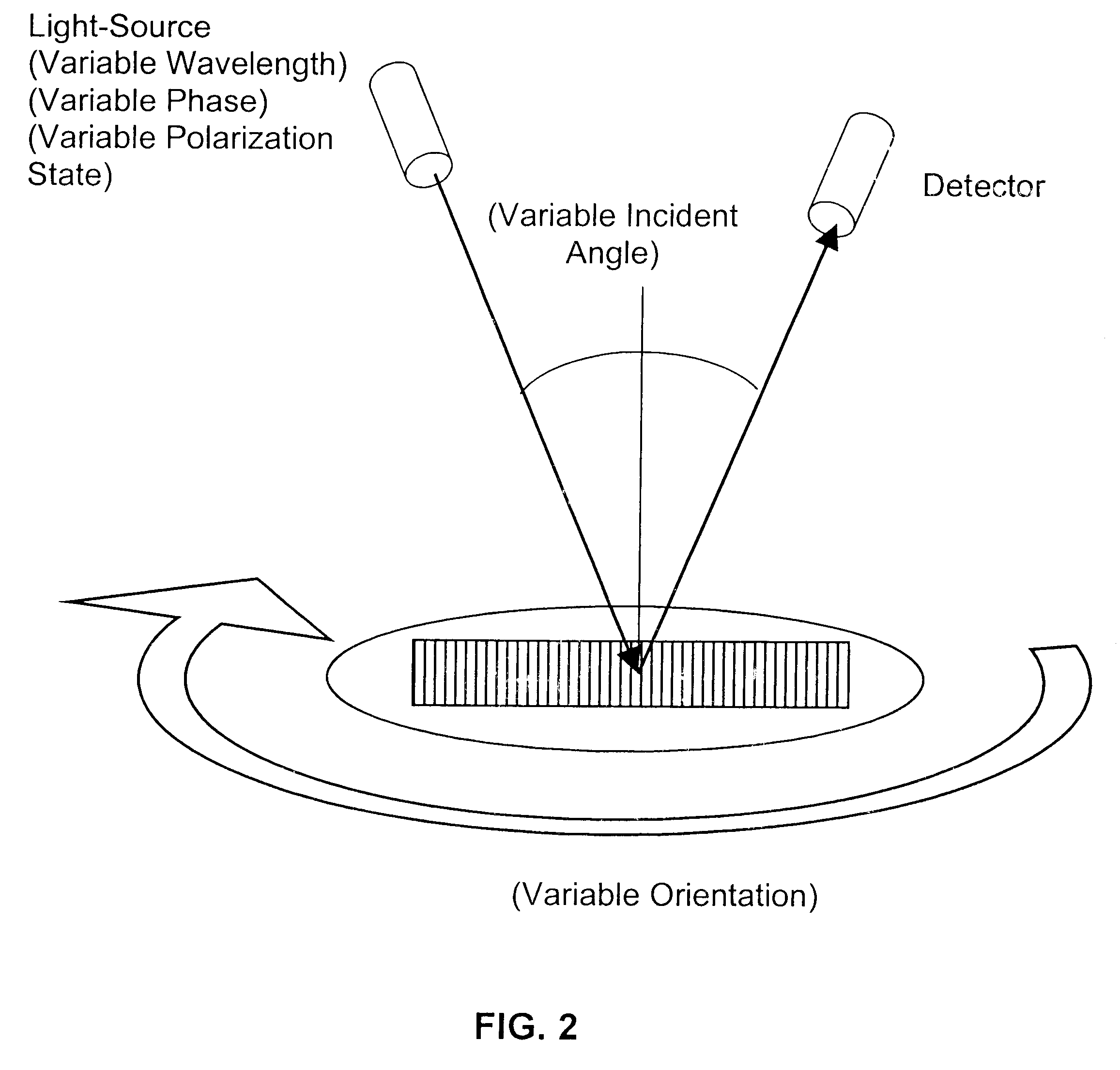
The present invention provides methods and devices for measuring parameters relating to a lithography device, and in a preferred embodiment, for determining the center of focus of a lithography device. In the methods, a series of diffraction signatures of different diffraction gratings are obtained, the diffraction gratings having been made utilizing the lithography device, and made employing a plurality of different focus settings, and optionally a plurality of different dose settings. The diffraction signatures are sequentially ordered, which ordering may be done subsequent to obtaining the diffraction signatures, such as in order of increase or decrease of focus setting, preferably in an equal increments, and the differences between diffraction signatures of adjacent focus setting diffraction gratings are determined. The differences are compared, optionally utilizing a metric such as a root mean square error method of analysis. The diffraction signatures will become closer togeth...


PUM

PropertyMeasurementUnit
thicknessaaaaaaaaaa
widthaaaaaaaaaa
widthaaaaaaaaaa

Abstract

The present invention provides methods for determination of parameters in lithographic devices and applications by diffraction signature difference analysis, including determination of center of focus in lithography devices and applications.

Description

1. Field of the Invention (Technical Field)The present invention relates to methods for determination of parameters in lithography applications by diffraction signature analysis, including determination of center of focus in lithography applications, such as for photoresist lithographic wafer processing.2. Background ArtNote that the following discussion refers to a number of publications by author(s) and year of publication, and that due to recent publication dates certain publications are not to be considered as prior art vis-a-vis the present invention. Discussion of such publications herein is given for more complete background and is not to be construed as an admission that such publications are prior art for patentability determination purposes.Lithography has a variety of useful applications in the semiconductor, optics and related industries. Lithography is used to manufacture semiconductor devices, such as integrated circuits created on wafers, as well as flat-panel display...

Claims


Application Information

Patent Timeline
Patent Type & Authority Patents(United States)
IPC IPC(8): G03F7/20G01M11/02H01L21/027
CPCG03F7/70591G03F7/70641G01B9/00
Inventor LITTAU, MICHAEL E.RAYMOND, CHRISTOPHER J.
Owner ONTO INNOVATION INC
Why Eureka
Try Eureka