Doctor blade

a blade and blade technology, applied in the field of blades, can solve the problems of reducing the productivity of printing process, unfavorable cleaning, and abrasion wear of the blade, and achieve the effects of reducing the smearing effect, improving the wear resistance of the blade, and eliminating the effect of smearing

Inactive Publication Date: 2002-08-13
BTG ECLEPENS
View PDF23 Cites 46 Cited by
  • Summary
  • Abstract
  • Description
  • Claims
  • Application Information

AI Technical Summary

Benefits of technology

Another object of the invention is to provide a doctor blade with extended lifetime thus improving operational productivity.
Yet another object of the invention is to provide a doctor blade with extended lifetime without changing the functionality of the anilox ceramic surface by any premature wear.
It has been found by experimental research that by the application of a ceramic onto a thin steel strip the wear resistance of the blade can be considerably improved without impairing the capacity of the inking roller to transfer the desired amount of ink. Thus, the improved wear resistance of the blade does not result in premature wear of the inking roller. Furthermore, the use of a ceramic coating on the blade eliminates any smearing effect which is typically encountered when steel blades without coating are used. Such smearing is caused by plastic flow of the steel contact surface against the ceramic inking roller. Moreover, the higher abrasive wear resistance of the ceramic as compared to steel greatly improves the lifetime of the blade when abrasive pigments are used.
Finally, the ceramic material which is less sensitive to load differences means that the typical edge wear encountered with steel blades will be significantly postponed. Accordingly, edge leakages are also significantly postponed.
It has been unexpectedly found that the ratio between the hardness of the ceramic coating on the blade and the hardness of the ceramic surface on the inking roller constitutes one of the key elements in the present invention. Thus, it has been found that the hardness ratio, hardness of blade ceramic versus hardness of ceramic roller, shall lie within the range from about 0.55 to about 0.8. Ratios lower than 0.55 do not result in significant advantages as compared to a steel blade which gives a typical ratio of 0.5 or lower. Ratios higher than 0.8 will start increasing wear on the ceramic inking roller. This could result in a decrease of the cell volume and thereby decreasing amount of transferred ink.

Problems solved by technology

The quick blade wear causes an uneven wiping over time.
Moreover, the productivity of the printing process is significantly reduced by such frequent blade changes.
Furthermore, depending on the type of ink and its content of pigment, abrasive wear of the blade can further decrease the lifetime, such as when using so called white ink containing TiO.sub.2 as a pigment which is very abrasive.
Excess of sliding wear, often related to high pressure load of the blade against the roll.
Edge wear of the blade on both sides of the chambered doctor blade leading to ink leakage.
Excess of abrasive wear when hard pigments are used in the printing operation.
In all these cases, as well as in combinations thereof, the sealing and wiping functions cannot be properly fulfilled.

Method used


Image

  • Doctor blade
  • Doctor blade

Examples


example 1

Abrasive Wear Resistance of Doctor Blades

This experiment was conducted in order to compare different brands of existing doctor blades with one selected ceramic material corresponding to the presently described findings.

A heavy wear trial was selected using the following parameters:

These conditions ware kept constant in all trials. For each test, the same blades wore chosen for both blade positions. The amount of wear was measured by width reduction of the blade. The table below presents the results.

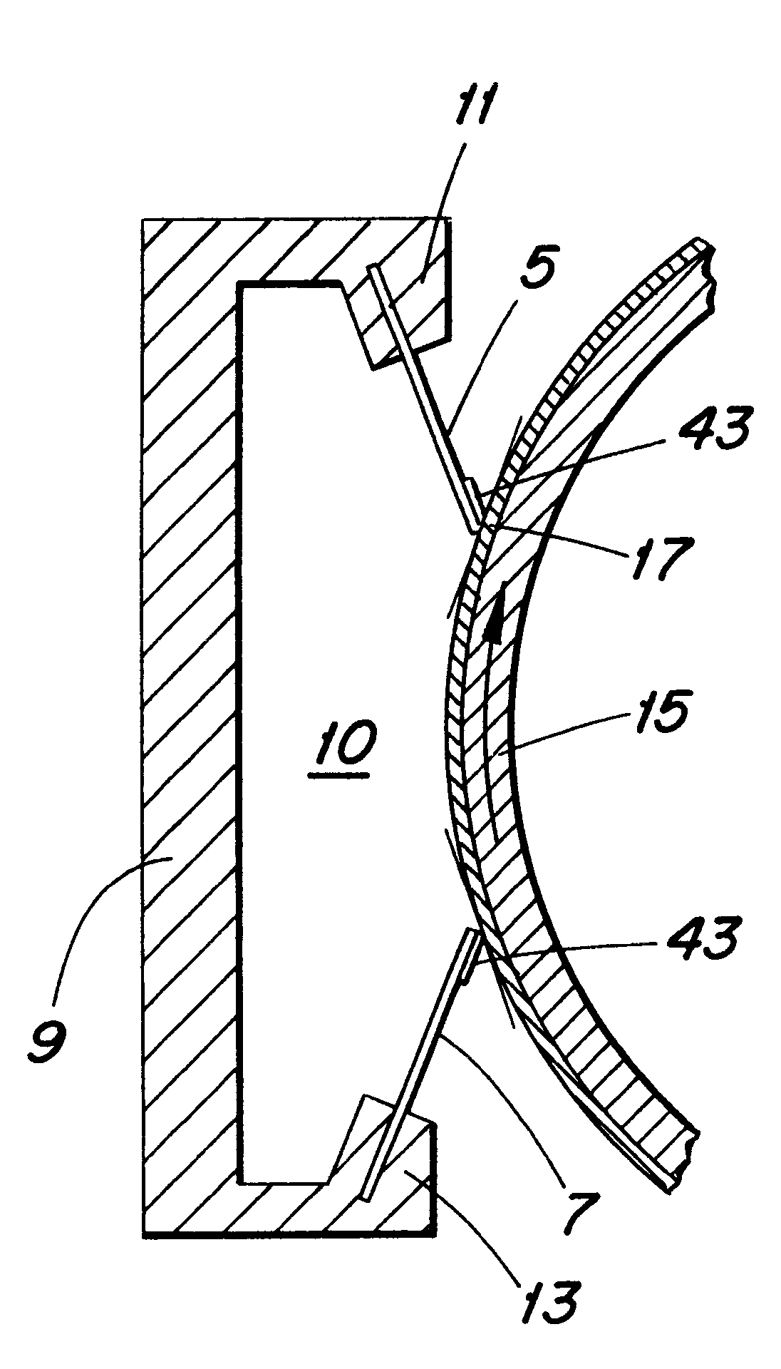
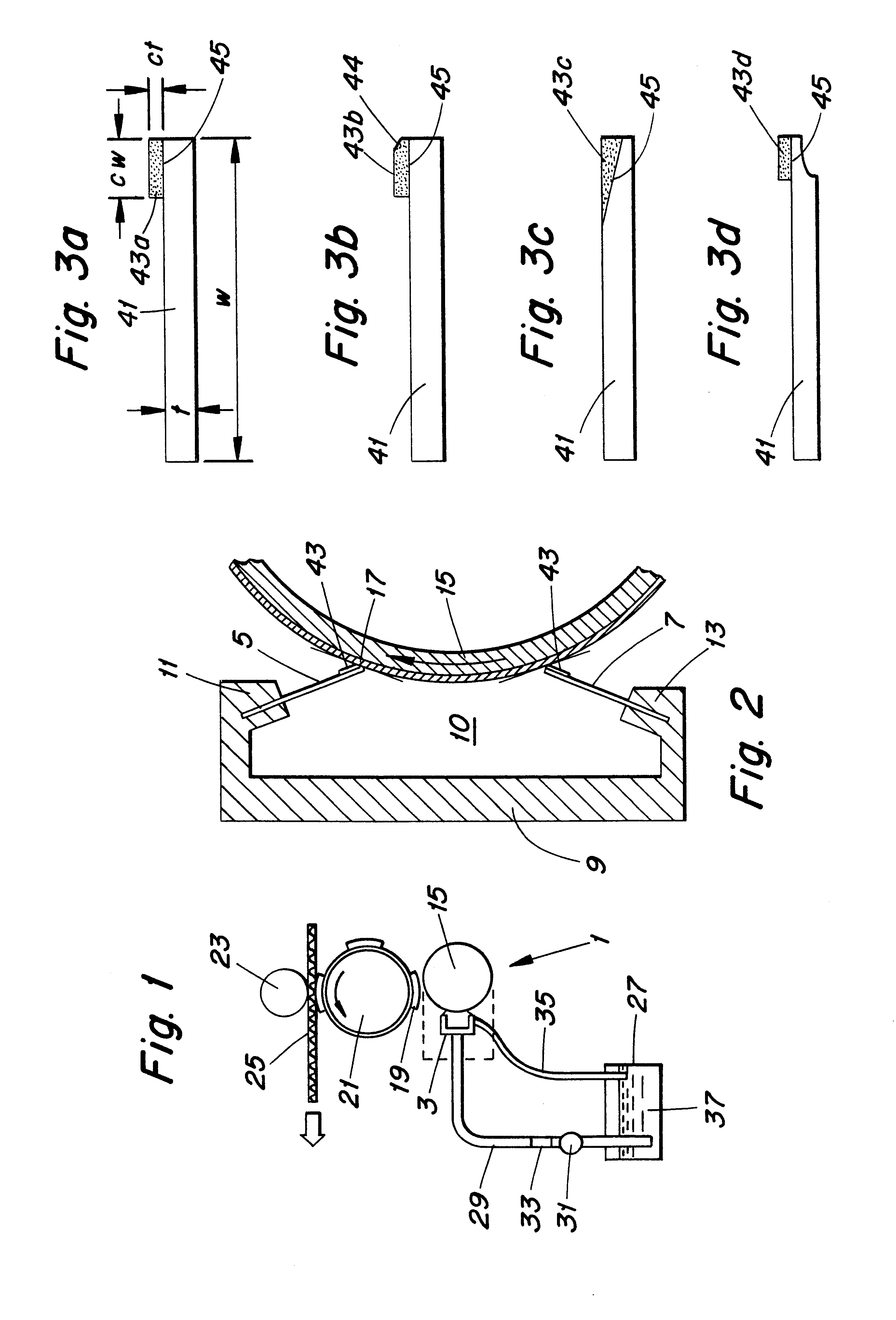
The ceramic tipped blade, type I, consists of a 50 .mu.m layer on top of a 0.150 mm thick steel doctor blade (see FIG. 41a). The material used is an APS thermally sprayed Al.sub.2 O.sub.3 --ZrO.sub.2 ceramic in the weight proportion of 60% Al.sub.2 O.sub.3 --40% ZrO.sub.2.

The micro-Vickers hardness is about 850 HV0.3 and the hardness ratio compared with the ceramic roll is 0.6 to 0.7.

The width of the ceramic layer was 8 mm.

In can be seen from these results that the amount of blade wear wa...

example 2

Anilox Wear Survey

In another experiment the same ceramic blade type I as used in Example 1 above was run on an experimental flexo test system for survey of the anilox wear, by measuring the cell volume before and after the test. The conditions were as follows:

The cell measurement performed by the URMI technique gave the following results:

Before: 7.4.+-.1 cm.sup.3 / m.sup.2

After: 7.6.+-.1 cm.sup.3 / m.sup.2

example 3

Real Printing Survey

In a third experiment another composition of the blade material (ceramic type II), according to the invention was used on a regular basis in a web flexo machine during several months (3 shift printing unit). Here both wear of blade and survey of the anilox roll were evaluated. The conditions were:

During this period, 14 mio meters have been printed. The URMI results as well as the cell depth show some slight decrease, which can be explained by the fact that the anilox was new at the beginning and therefore may present some initial higher wear until the bridge between the cells are better defined. It can also be concluded that the ceramic tipped blade here were at the upper hardness ratio acceptable and some wear really occurs on the anilox roll.

In this case, the selected ceramic tipped blade (type II) was as follows:

The lifetime of the blade according to the invention reached 16 days non-stop as record and about 8 days in average.

Detailed Description of the Blade

A...


PUM

PropertyMeasurementUnit
thicknessaaaaaaaaaa
widthaaaaaaaaaa
widthaaaaaaaaaa

Abstract

A doctor blade for direct contact with a ceramic roll surface. The doctor blade includes a strip of metallic carrier material, which, along one edge section is provided with a ceramic coating. The ceramic coating on the blade has a hardness ranging from approximately 850 to 950 microvickers, thereby substantially increasing wear resistance of the blade without substantially increasing wear on the ceramic roll surface for which the blade is adapted for use.

Description

The present invention relates to doctor blades for direct contact with inking rollers provided with ceramic coatings. In particular, the doctor blade is useful for flexographic printing. The invention also provides for a doctor blade unit and a flexographic printer operating with the new doctor blade.BACKGROUND AND STATE OF THE ARTAlthough the invention is applicable to all doctor blades for direct contact with inking rollers provided with a ceramic coating the invention will be described mainly with reference to so called flexographic printing.In the art of flexographic printing the amount of ink is volumetrically metered by the use of a so called anilox roller. This roller is usually constituted by a metal cylinder onto which a ceramic coating has been applied. The ceramic is normally applied by a thermal spray process. For the purpose of volumetric metering of the ink the ceramic surface is laser engraved in order to create uniform cells for carrying and transferring an even ink ...

Claims


Application Information

Patent Timeline
Patent Type & Authority Patents(United States)
IPC IPC(8): B41F31/02B41F31/08B41F31/20
CPCB41F31/027B41N10/005
Inventor PEREZ, JAIMECREVOISIER, PHILIPPEFRETI, SILVANO
Owner BTG ECLEPENS
Why Eureka
Try Eureka