Surface-mounted antenna and wireless device incorporating the same

a wireless device and antenna technology, applied in the structure of resonant antennas, radiating elements, protective materials, etc., can solve the problems of difficult to obtain bandwidth allocated to applications, difficult to control the frequency bandwidth independently from each other, and many problems in handling multi-bands, so as to achieve easy adaptability and easy to broaden the use of frequency bands.

Inactive Publication Date: 2002-08-13
MURATA MFG CO LTD
View PDF9 Cites 28 Cited by
  • Summary
  • Abstract
  • Description
  • Claims
  • Application Information

AI Technical Summary

Benefits of technology

In the above structure, at least the three radiation electrodes are formed on a surface of the dielectric base member so that the antenna is easily adaptable to multi-bands. Moreover, by setting the current-vector directions of the radiation electrodes and the distances between the radiation electrodes according to needs, the resonance waves of the radiation electrodes can be controlled independently from each other. Thus, for example, only one frequency band of required frequency bands is selected to set in a multi-resonance state so that broadening of the used frequency band can be very easily achieved.

Problems solved by technology

Such an antenna, however, has many problems in handling multi-bands.
As a result, it is difficult to obtain bandwidths allocated to the applications.
In addition, it is extremely difficult to control the frequency bandwidths independently from each other.
These are critical problems to be solved.

Method used


Image

  • Surface-mounted antenna and wireless device incorporating the same
  • Surface-mounted antenna and wireless device incorporating the same
  • Surface-mounted antenna and wireless device incorporating the same

Examples


first embodiment

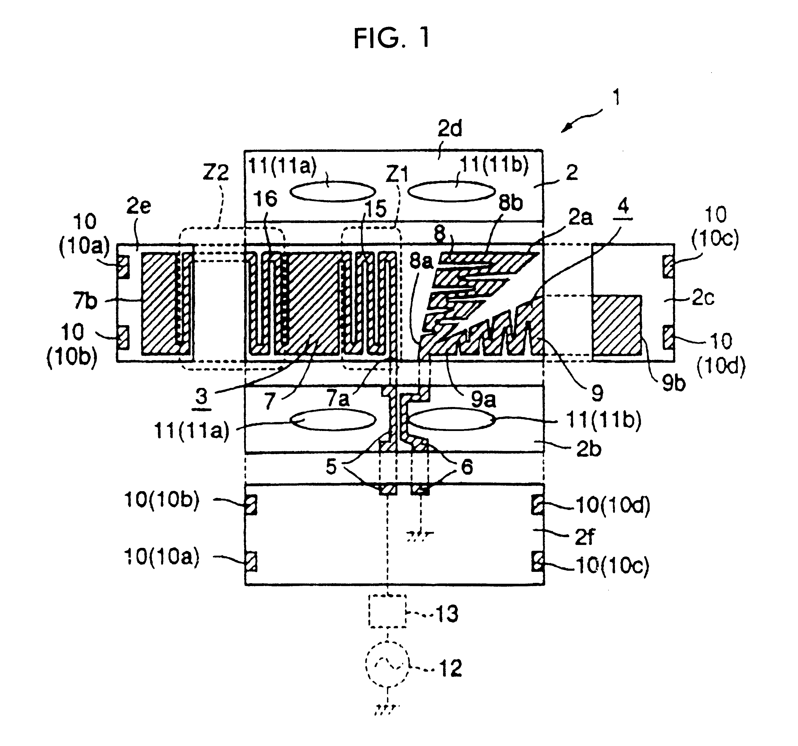
FIG. 1 shows a developed view of a surface-mounted antenna according to the invention. In a surface-mounted antenna 1 shown in FIG. 1, on a rectangular-parallelepiped dielectric base member 2, a feeding element 3 and a non-feeding element 4 are arranged with a distance therebetween. Most uniquely, the non-feeding element 4 is formed as a branched element.

That is, as shown in FIG. 1, on a front side surface 2b of the dielectric base member 2, a feeding terminal 5 and a ground terminal 6, which are extended from a bottom surface 2f in an upper direction in the figure, are arranged with a distance therebetween. In addition, on an upper surface 2a of the dielectric base member 2, there is formed a radiation electrode 7 of the feeding side continued to the feeding terminal 5. The radiation electrode 7 of the feeding side is extended from the upper surface 2a to a left side surface 2e in the figure. A top end 7b of the extended radiation electrode 7 of the feeding side is open-circuited. ...

second embodiment

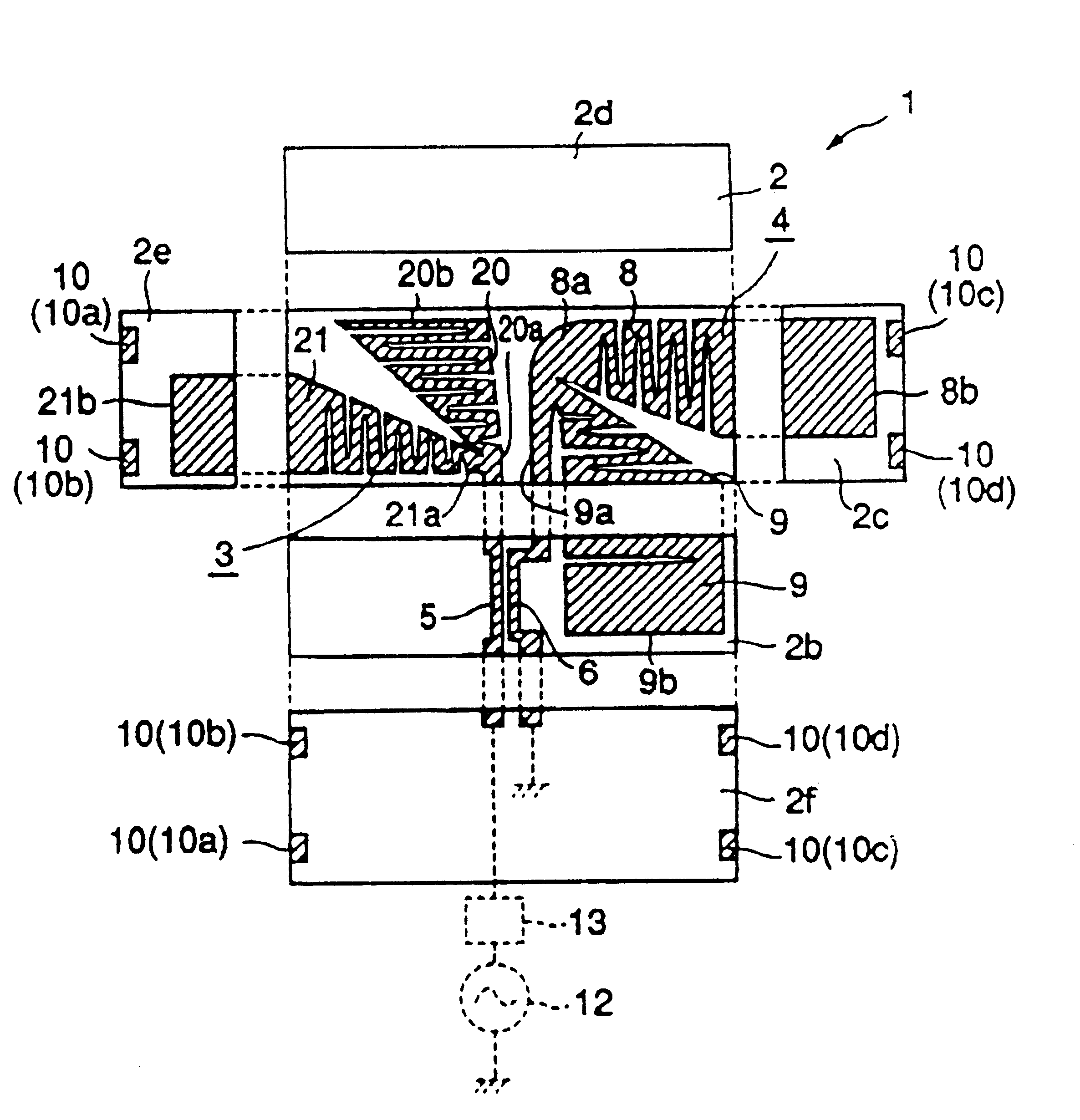
Specifically, as shown in FIG. 4, on an upper surface 2a of a dielectric base member 2, feeding-side first and second radiation electrodes 20 and 21 are branched from a feeding terminal 5 formed on a front side surface 2b and are extended with a distance therebetween. In this second embodiment, the feeding element 3 is constituted of the feeding terminal 5 and the feeding-side first and second radiation electrodes 20 and 21.

The feeding-side first and second radiation electrodes 20 and 21 are extended in a direction in which the distance between the electrodes 20 and 21 is expanded from the feeding terminal 5. As a result, the mutual interference between the feeding-side first and second radiation electrodes 20 and 21 can be prevented. A top end 20b of the feeding-side first radiation electrode 20 is open-circuited. The feeding-side second radiation electrode 21 is further extended from the upper surface 2a to a left side surface 2e, and a top end 21b of the extended electrode 21 is ...

third embodiment

the surface-mounted antenna having the unique structure shown in each of the above embodiments is incorporated in the portable wireless device 26. Thus, with only the single surface-mounted antenna 1 incorporated, the signals of different frequency bands can be transmitted and received. As a result, it is unnecessary to incorporate multiple antennas according to the number of frequency bands required to transmit and receive signals of the different frequency bands, thereby contributing to further miniaturization of the portable wireless device 26. In addition, the wireless device can also have highly reliable antenna characteristics.

However, the present invention is not restricted to the above-described embodiments, and various modifications can be made. For example, in the first embodiment, of the feeding element 3 and the non-feeding element 4, only the non-feeding element 4 is formed as a branched element. In the second embodiment, both the feeding element 3 and the non-feeding e...


PUM


Abstract

A multi-band surface-mounted antenna is formed by disposing a feeding element and a non-feeding element with a distance therebetween on a dielectric base member. The feeding element is formed by extending a feeding radiation electrode from a feeding terminal. The non-feeding element is a branched element formed by branching and extending a first radiation electrode and a second radiation electrode of the non-feeding side from a ground terminal side. The single surface-mounted antenna includes the three radiation electrodes. Thus, the antenna can be easily adapted to multi-bands. In addition, the resonance waves of the three radiation electrodes can be controlled mutually independently. As a result, only a frequency band selected from a plurality of required frequency bands is brought into a multi-resonance state so that the frequency band can be broadened.

Description

1. Field of the InventionThe present invention relates to surface-mounted antennas capable of transmitting and receiving the signals of different frequency bands and wireless devices incorporating the same.2. Description of the Related ArtRecently, there has been a demand for wireless devices on the market, in which a single wireless device such as a mobile phone needs to be adaptable to multi-bands for a plurality of applications, for example, the global system for mobile communications (GSM) and the digital cellular system (DCS), the personal digital cellular (PDC) and the personal handyphone system (PHS), and the like. In order to meet the demand, there are provided various antennas. In these cases, the signals of different frequency bands can be transmitted and received by using only a single antenna.Such an antenna, however, has many problems in handling multi-bands. Particularly, in required multiple frequency bands, in a region closer to the high-frequency side, the frequency...

Claims


Application Information

Patent Timeline
Patent Type & Authority Patents(United States)
IPC IPC(8): H01Q1/24H01Q5/00H01Q9/04H01Q19/00H01Q1/38H01Q21/30H01Q5/10H01Q5/364H01Q5/378
CPCH01Q1/243H01Q1/38H01Q9/0414H01Q5/378H01Q5/321H01Q5/371H01Q19/005H01Q5/00
Inventor NAGUMO, SHOJIKAWAHATA, KAZUNARITSUBAKI, NOBUHITOONAKA, KENGOISHIHARA, TAKASHI
Owner MURATA MFG CO LTD
Why Eureka
Try Eureka