

Liquid-cooled power semiconductor device heatsink
a technology of heatsinks and semiconductor devices, which is applied in the direction of lighting and heating apparatus, power cables, cables, etc., can solve the problems of power electronic devices being subject to higher operating temperatures, localized hot spots can occur, and heat transfer from power electronic devices is diminished to some degr
- Summary
- Abstract
- Description
- Claims
- Application Information
AI Technical Summary
Benefits of technology
Problems solved by technology
Method used
Image

Examples
Embodiment Construction
1. Field of the Invention
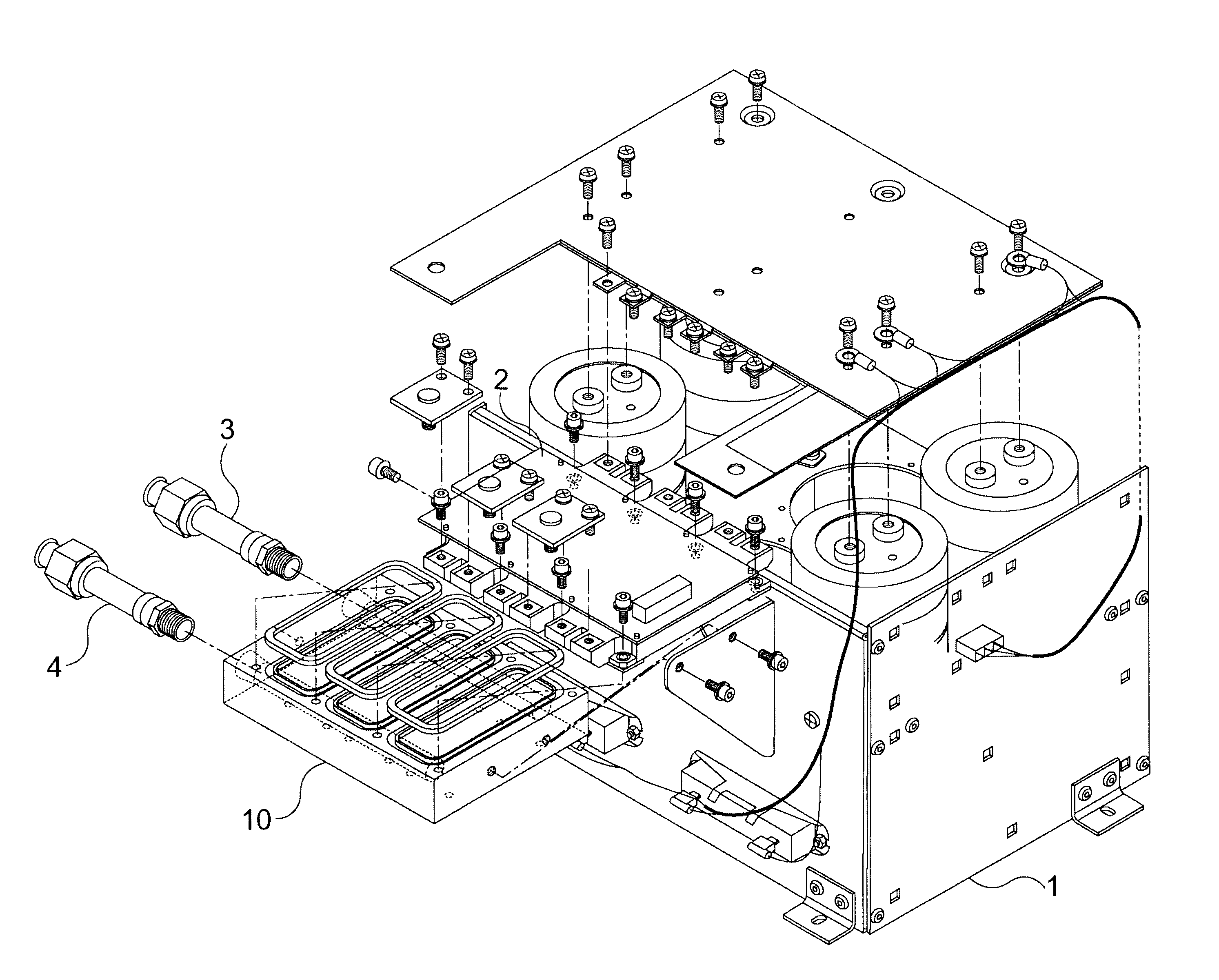
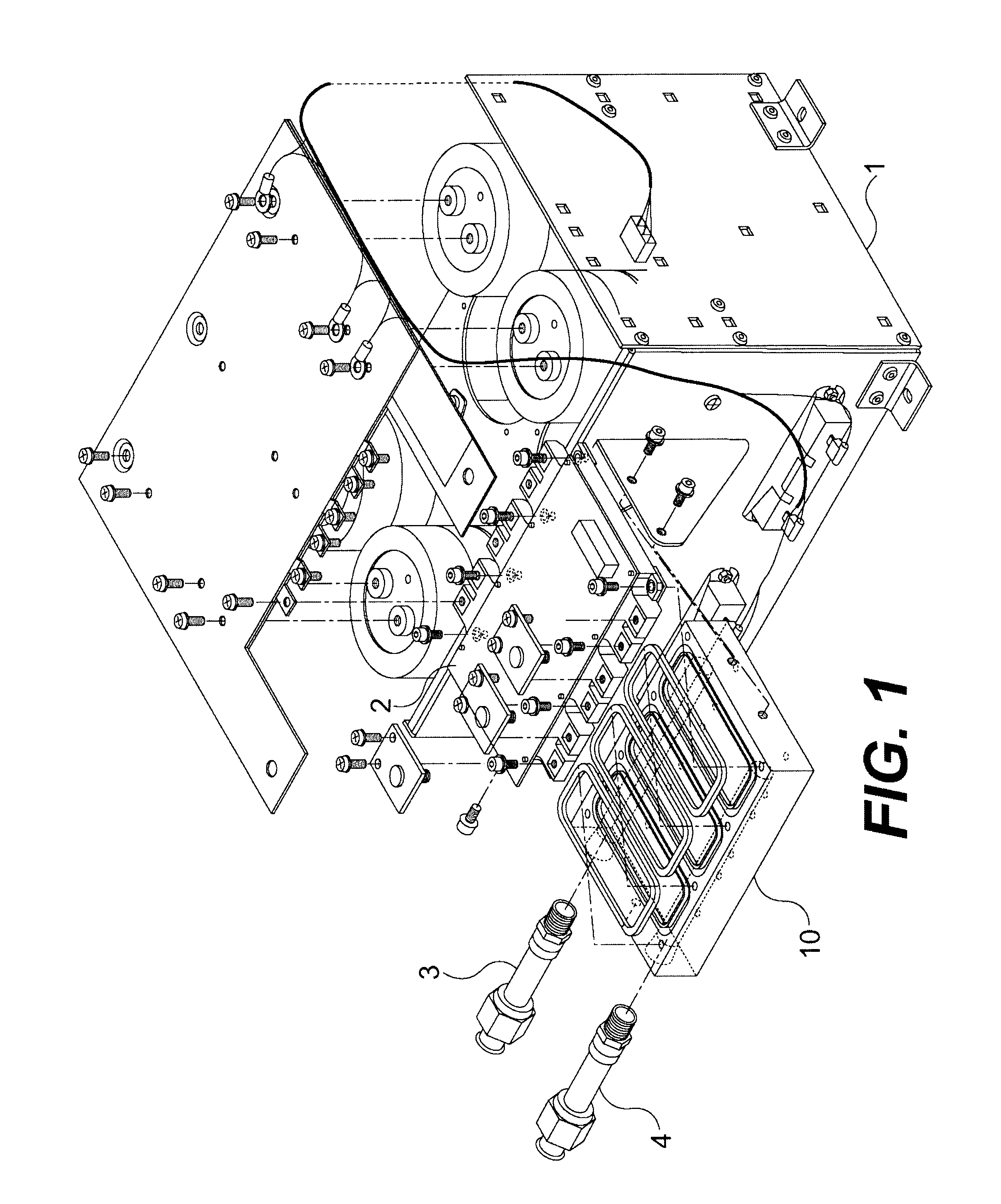
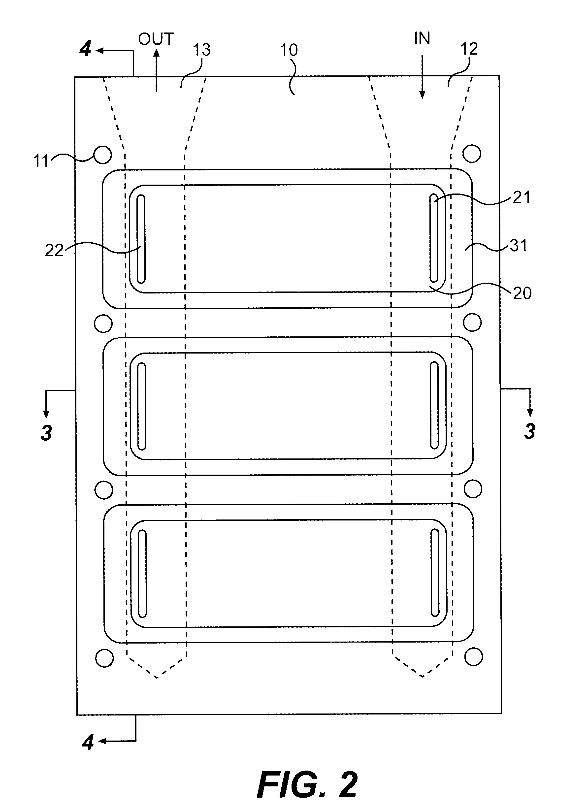
The present invention generally relates to heatsinks for cooling power electronic devices, especially devices used to provide power to an induction motor in an HVAC system. More particularly, this invention relates to a heatsink whereby cooling fluid comes in direct contact with the device to be cooled via a system of channels and wells over which the device is mounted.
2. Background of the Invention
Power electronic devices such as insulated gate bipolar transistors (IGBTs) and silicon-controlled rectifiers (SCRs) are typically cooled by mounting the devices within a housing which is secured to a heatsink or "cold plate". Cold plates are typically formed from a material which is highly thermally conductive, such as aluminum or copper, enabling the cold plate to readily conduct heat generated by the devices away from the devices and to the environment. Generally, heat is conducted by the cold plate to a structure which is designed to transfer the heat to the s...
PUM
 Abstract
Description
Claims
Application Information