Liquid ejection apparatus using air flow to remove mist

a liquid ejection and air flow technology, applied in printing and other directions, can solve the problems of not being able to achieve both high density images, inability to achieve color images with sufficient fastness properties or satisfactorily high print quality, and bleeding on printing media

Inactive Publication Date: 2002-08-20
CANON KK
View PDF46 Cites 28 Cited by
  • Summary
  • Abstract
  • Description
  • Claims
  • Application Information

AI Technical Summary

Problems solved by technology

However, in a printing apparatus employing such ink-jet system, if a printing medium called plain paper is used, bleeding occurs on the printing medium upon deposition of water or so forth due to insufficiency of resistance of a printed image to water.
Also, upon color printing on the plain paper, it has not been possible to achieve both of a high density image without causing feathering and an image without bleeding between colors.
Therefore, it may be possible that a color image with sufficient fastness property or satisfactorily high print quality cannot be obtained.
However, the water resistance of the ink is still insufficient.
Also, such water resistive ink is difficult to dissolve in water after once dried in principle, and it has a tendency to easily cause plugging in ejection openings or so forth in an ink-jet printing head.
On the other hand, a construction of the apparatus required for preventing plugging of the ejection openings becomes complicated.
On the other hand, it has been well known that the ink-jet printing system encounters the following problem.
When a large amount of the mist is deposited around the ejection opening, or when paper dust or other foreign matter adheres on the mist deposited around the ejection openings, ink ejection can be affected, causing variation in the ejecting direction of the ink droplet (hereinafter also simply referred to as "deflection"), failure of ejection of the ink droplet and so forth.
Secondly, in the ink-jet head, while ejection is not performed, particularly when a non-ejection state is maintained for a long period, viscosity of the ink in the ejection openings can increase and the ink can solidify.
Also in this case, deflection, ejection failure or so forth can be caused.
However, in the latter case, since the flying direction of the ejected ink droplet can be disturbed by the air flow...

Method used


Image

  • Liquid ejection apparatus using air flow to remove mist
  • Liquid ejection apparatus using air flow to remove mist
  • Liquid ejection apparatus using air flow to remove mist

Examples


first embodiment

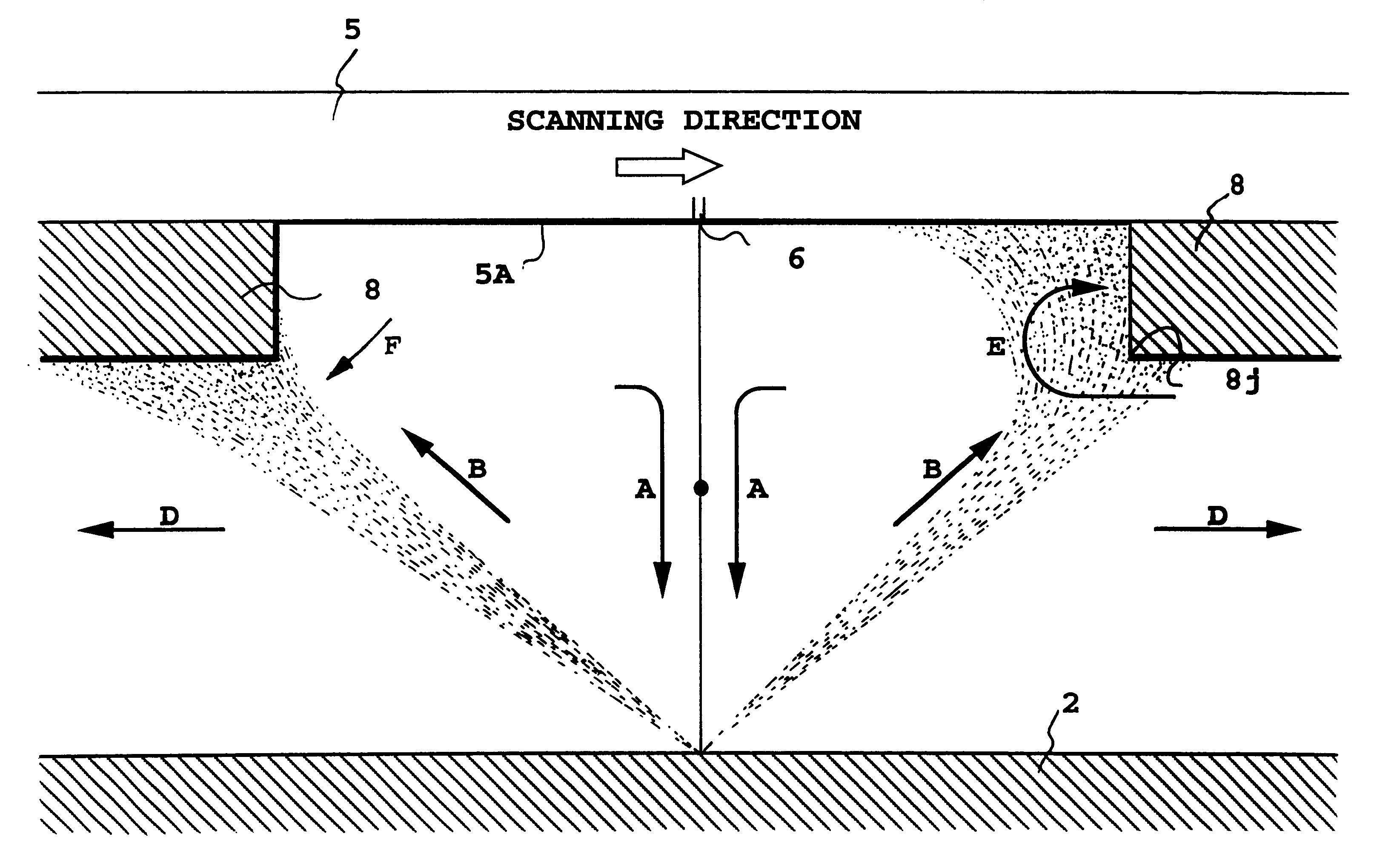
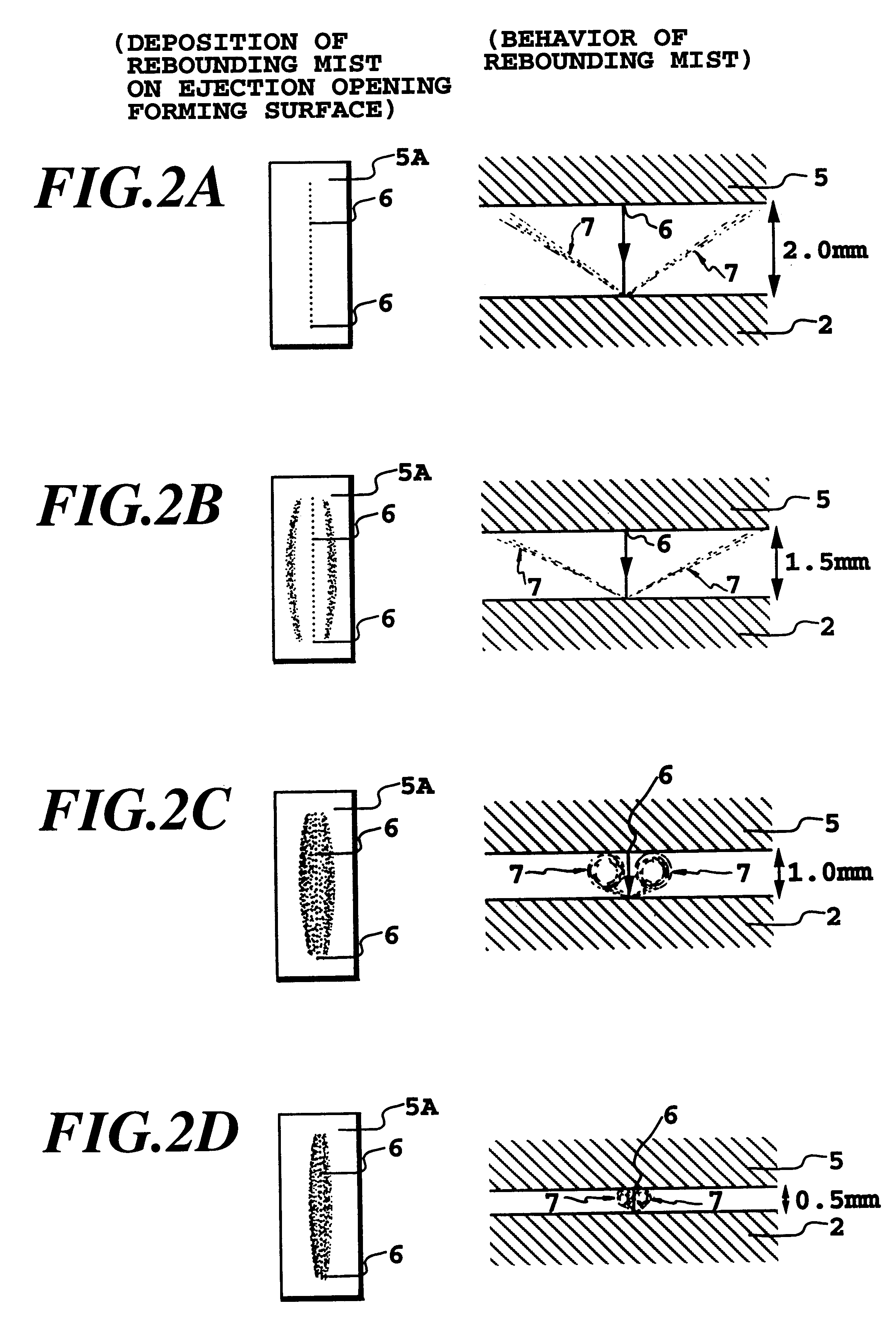
More specifically, a problem encountered upon occurrence of rebounding mist is that an insoluble matter in the rebounding mist is deposited on an ejection opening portion of an ink-jet head and / or a portion in the vicinity thereof to cause serious ejection failure. Accordingly, in a first example of the present invention, there is provided a cover for covering a region of the head, which region is decided by study of behavior of the rebounding unit so that the insoluble matter can be prevented from being deposited on a ejection opening forming surface per se as well as on the ejection openings or the portion in the vicinity thereof or an amount of the insoluble matter deposited can be reduced.

When such a cover is provided, a range to provide the cover means becomes a problem to study. Therefore, discussion will be given hereinafter with respect to study for the range to be covered.

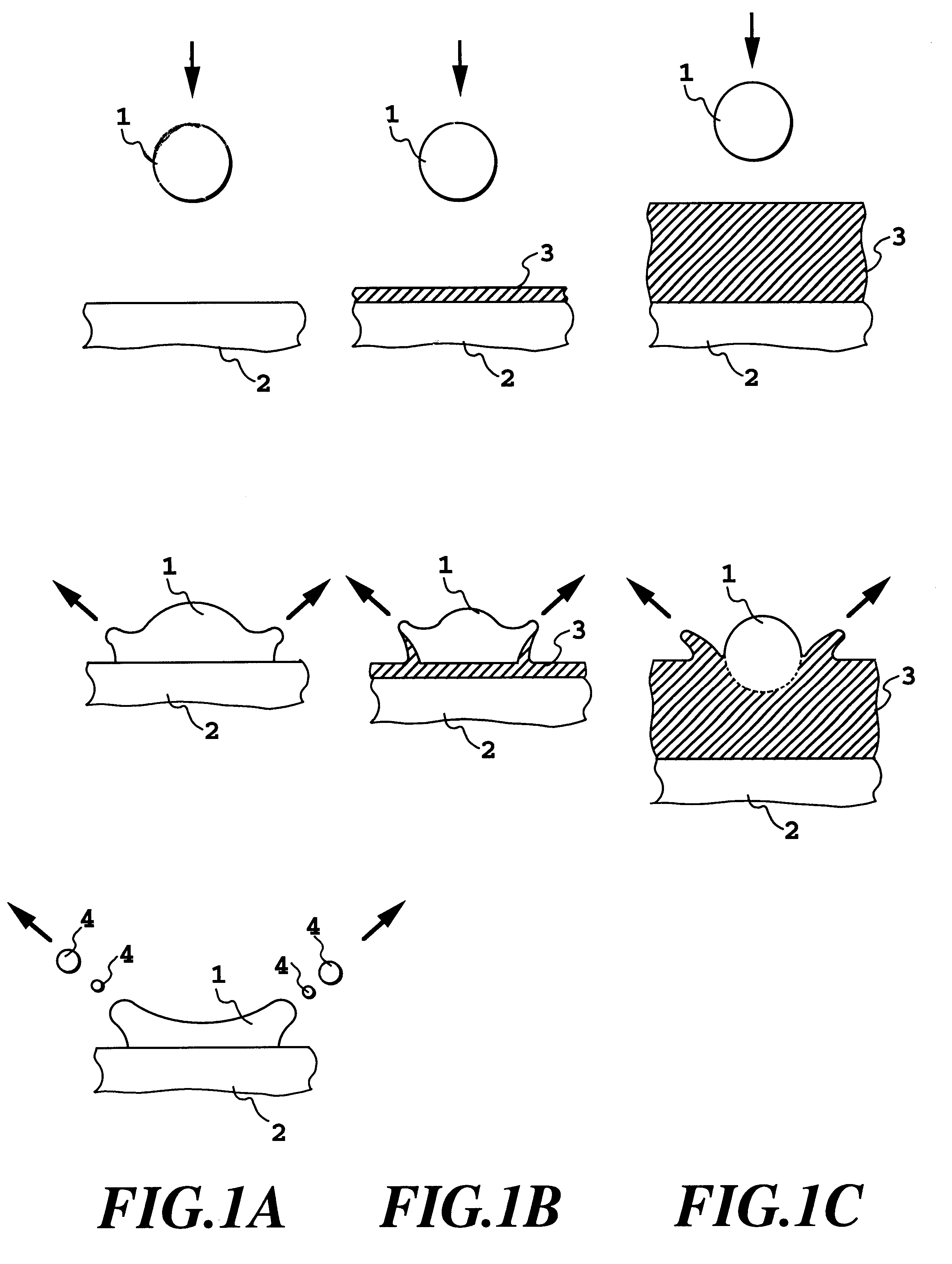
FIGS. 1A to 1C are diagrammatic illustrations for explaining behavior in rebounding or so forth caused ...

second embodiment

the present invention will be discussed hereinafter more concretely. The ink-jet printing apparatus, the processing liquid and so forth to be employed in the shown embodiment are similar to those employed in the first embodiment. Therefore, they will not be discussed again, to avoid redundant discussion and to keep the disclosure simple enough to facilitate clear understanding of the invention.

The shown embodiment of the head unit is similar to that illustrated in FIG. 20. FIG. 25 is an illustration showing a condition where the head unit 102 performs the printing operation. It should be noted that the head units 102 for Y, M and C inks are omitted from the illustrations.

In the shown embodiment, in respective ink-jet heads, ejection openings 206 are arranged in two arrays. Arrangements of ejection openings in respective arrays are offset by 1 / 2 of the pitch of the ejection openings relative to each other. Because of this, it becomes possible to perform printing at twice the resoluti...

third embodiment

(THIRD EMBODIMENT)

A third embodiment of the present invention employs a cover plate partly covering the ejection opening forming surface for lowering the absolute amount of the insoluble substance deposited on the ejection opening forming surface of the ink-jet head (ejecting means). In addition, by utilizing such construction or by providing the stepped portion separately from the foregoing construction, control of position of the insoluble substance utilizing air flow becomes possible. Then, particularly in the third embodiment, the effect of wiping can be maximized.

More specifically, the shown embodiment is worked out in the novel viewpoint that, by the air flow generated upon scanning of the ink-jet head provided with the cover plate or the step similarly to the former embodiment, the deposition range of the insoluble substance can be controlled, and the range of deposition is differentiated depending upon the cause of mist generated by ejection of the ink and the processing liq...


PUM


Abstract

A region to be covered by a cover plate on an ejection opening forming surface of an ink-jet head or an ink-jet head to which the cover plate is installed are determined, on a basis of content of a rebounding mist generated upon ejection of an ink and a processing liquid in overlaying fashion. By this, in the ink-jet printing apparatus performing printing by ejecting the ink and the processing liquid for making the ink insoluble, deposition of the insoluble substance contained in the rebounding mist generated upon ejection of an ink and a processing liquid in overlaying fashion can be successfully prevented.

Description

1. Field of the InventionThe present invention relates to a head unit, an ink-jet cartridge and a liquid ejection apparatus. Particularly, the invention relates to an ink-jet head unit, an ink-jet cartridge and an ink-jet printing apparatus for performing,printing with ejecting an ink and a printing ability improving liquid (hereinafter simply referred to as "processing liquid") which makes a coloring material in the ink insoluble or coagulates the coloring material.The present invention is applicable for all of devices or apparatuses which employ a paper, a cloth, a leather, a non-woven fabric, an OHP sheet and so forth, and even a metal and so forth as media (hereinafter simply referred to as "printing medium") receiving inks and the printing ability improving liquid. Concretely, the present invention is applicable for an office machine, such as a printer, a copy machine and a facsimile machine, an industrial production machine and so forth.2. Description of the Related ArtConvent...

Claims


Application Information

Patent Timeline
IPC IPC(8): B41J2/21
CPCB41J2/2114
Inventor MURAKAMI, SHUICHIKOITABASHI, NORIBUMIUETSUKI, MASAYANAKAJIMA, YOSHINORI
Owner CANON KK
Why Eureka
Try Eureka