Shock absorber with cup-shaped stop cap

a technology of shock absorber and stop cap, which is applied in the direction of vibration dampers, resilient suspensions, vehicle components, etc., can solve the problems of affecting the adjustment of shock absorbers, and introducing large forces into the support elements

Inactive Publication Date: 2002-09-03
WEFORMA
View PDF24 Cites 22 Cited by
  • Summary
  • Abstract
  • Description
  • Claims
  • Application Information

AI Technical Summary

Benefits of technology

The above objects have been achieved according to the invention in a shock absorber including a housing, a piston axially slidably arranged in the housing, a piston rod connected to the piston and extending through a seal at one end of the housing, and a contact or stop element that is arranged on an end of the piston rod opposite the piston and that is adapted to be contacted by a moving load component that is to be slowed down and stopped. The moving load component bearing against the contact or stop element causes the piston to be axially moved in the housing and thereby to displace a hydraulic fluid through a throttling arrangement, so as to dissipate the kinetic energy of the moving load component.
With the inventive arrangement of a shock absorber, in the case of a large moving load bearing against the stop element, the arising forces will be transmitted directly from the stop element into the support element which is a rigid part of the shock absorber housing itself, once the piston and parts connected thereto have reached the end limit of the maximum allowable travel. In this manner, there is no danger of applying a load from the stop element onto the adjusting ring, which might otherwise damage the rotatable adjusting ring. The rigid positive stop and contact of the stop element against the rigid support element of the housing itself enables an especially large force transmission and force introduction directly from the stop element into the robust housing of the shock absorber, without causing any possible damage of the components of the shock absorber or any interference or interruption of the proper functioning thereof.
Even though the adjusting ring protrudes axially from the first end of the shock absorber housing, and is thus the furthest outwardly protruding part of the shock absorber housing or body, the adjusting ring is completely protected and will not have any forces introduced thereto when the stop cap bears against the support surface at this end of the housing. Thus, the invention provides the advantages of a very simple adjustability of the damping characteristic of the shock absorber by simply turning the adjusting ring (when it is exposed, i.e. uncovered by the stop cap being moved to a position away from the end limit position in which the stop cap encloses the adjusting ring). In combination therewith, the invention provides the advantages of a positive mechanical stop to limit the travel of the piston and of the stop element connected thereto, with a positive mechanical load introduction from the stop cap directly into the robust housing of the shock absorber.

Problems solved by technology

A disadvantage of such a conventional arrangement is that very great forces will be introduced into the support element, i.e. the adjusting ring in the conventional shock absorber, when a large load has contacted and pushed against the stop element and thereby pushed the piston through its maximum allowable stroke.
As a result, the adjusting ring is very heavily loaded, for example even to the extent that plastic deformations arise in the adjusting ring or in various force transmitting or bearing components within the shock absorber housing.
As a result, the adjustability of the shock absorber is negatively influenced or even made impossible.

Method used


Image

  • Shock absorber with cup-shaped stop cap
  • Shock absorber with cup-shaped stop cap
  • Shock absorber with cup-shaped stop cap

Examples


Embodiment Construction

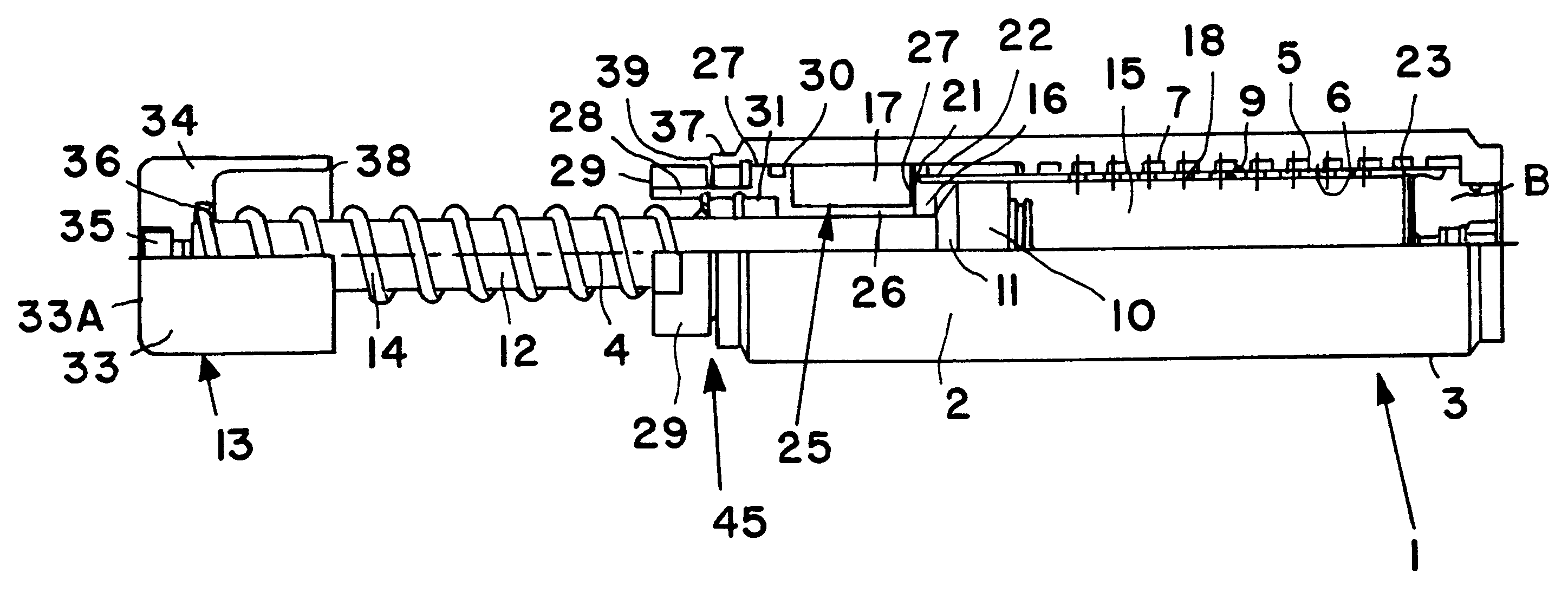
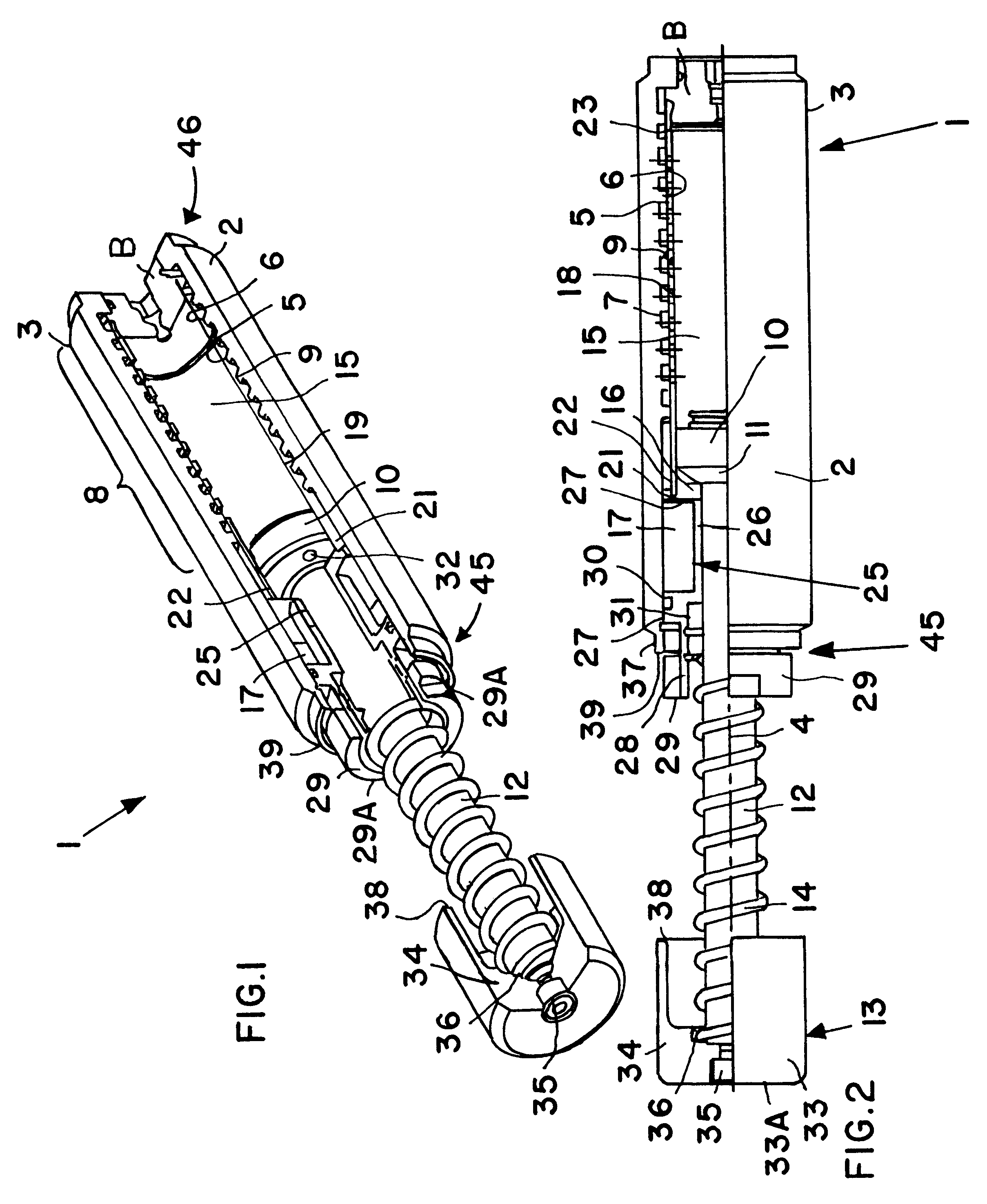
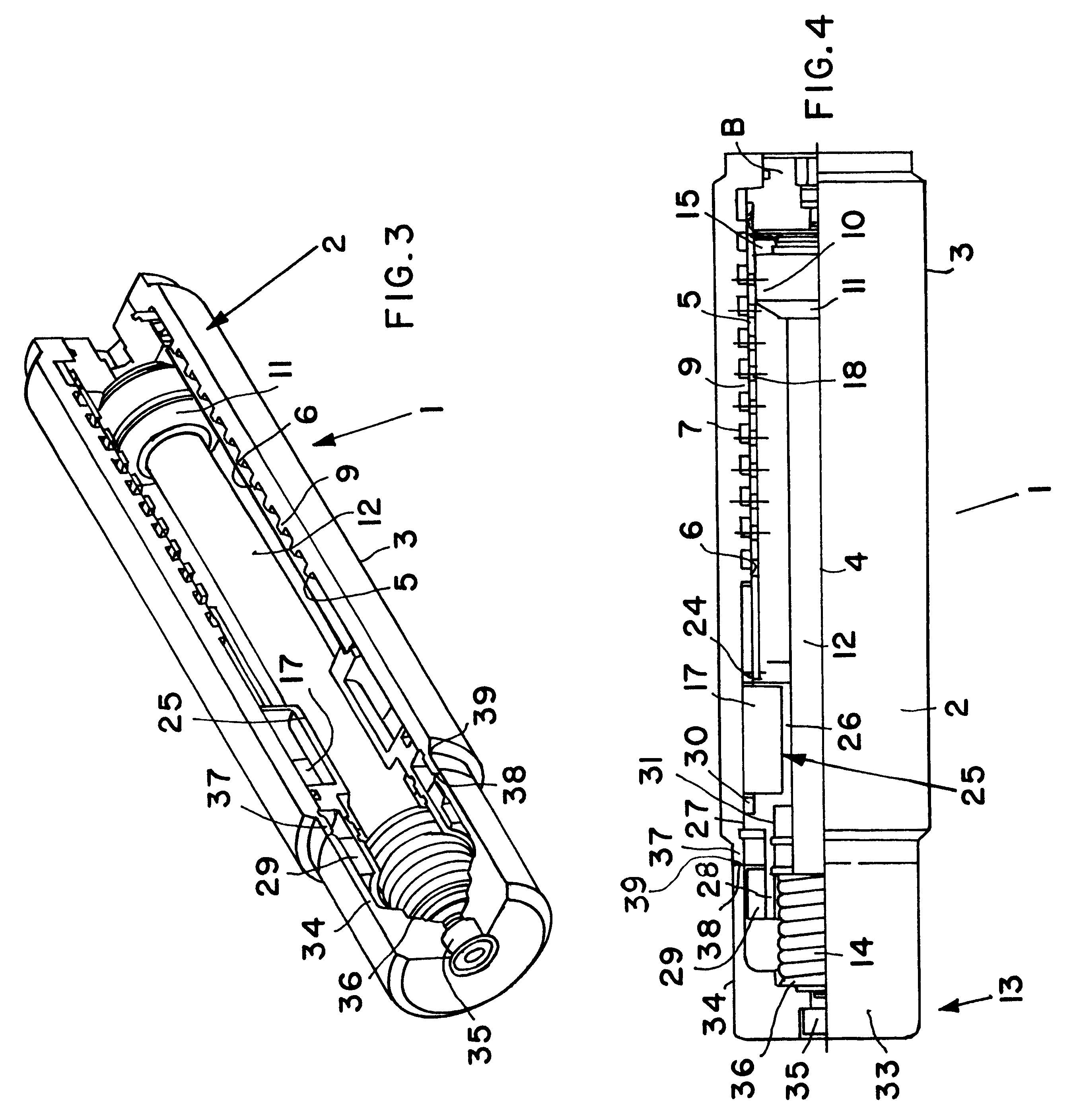
The shock absorber 1 shown in FIGS. 1 to 4 comprises a cylindrical pipe-shaped housing 2, of which the outer cylindrical surface 3 is preferably entirely and continuously provided with an external threading which allows the shock absorber 1 to be mounted and secured in any suitable mounting bracket or machine component or the like. Other means for mounting the shock absorber may be provided instead of or in addition to the external threading. The shock absorber 1 further comprises a pressure pipe 5 arranged in the housing 2 coaxially relative to the lengthwise axis 4 thereof. The pressure pipe 5 in this embodiment is generally a hollow cylindrical sleeve open at both ends thereof, but alternatively it could be closed at one end thereof. In the latter embodiment, the closed end of the pressure pipe 5 can simultaneously form the closed end of the housing 2.

A spiral groove 7 is formed in an inner cylindrical surface 6 of the housing 2, whereby this groove 7 extends over an axial range ...


PUM

PropertyMeasurementUnit
dampingaaaaaaaaaa
forceaaaaaaaaaa
inner diameteraaaaaaaaaa

Abstract

A shock absorber includes a housing, a piston slidable in the housing, a piston rod extending outwardly from the piston, a cup-shaped stop cap secured to the free end of the piston rod, and an adjusting ring which protrudes from the end of the housing and can be rotated to adjust the damping coefficient by adjusting the open cross-section of throttle openings through which a hydraulic fluid is displaced by the piston. When a load pushes against the stop cap, the maximum travel is limited by the stop cap bearing directly against a rigid end ring of the housing. The load forces are introduced directly from the stop cap into the housing, without applying any loads onto the adjusting ring or other components. The adjusting ring and a return spring coaxially on the piston rod are accommodated within the stop cap in the fully retracted position.

Description

PRIORITY CLAIMThis application is based on and claims the priority under 35 U.S.C. .sctn.119 of German Patent Application 100 28 586.4, filed on Jun. 14, 2000, the entire disclosure of which is incorporated herein by reference.The invention relates to a shock absorber for taking up the impact shock of a moving component, and then slowing down and stopping the component. The shock absorber includes a housing, a piston axially slidably arranged in the housing, a piston rod connected to the piston and extending outwardly through a seal at an end of the housing, and a contact or stop element connected to the end of the piston rod opposite the piston. A moving load component, which is to be slowed down and stopped, strikes against the stop element, whereupon the piston is slidingly moved while displacing a hydraulic fluid through a throttling arrangement to dissipate the kinetic energy. A mechanical support element limits the maximum stroke of the piston.BACKGROUND INFORMATIONThe above d...

Claims


Application Information

Patent Timeline
Patent Type & Authority Patents(United States)
IPC IPC(8): F16F9/58F16F9/32A61K48/00F16F9/44F16F9/48
CPCF16F9/3242F16F9/58
Inventor SCHMIDT, ARMIN
Owner WEFORMA
Why Eureka
Try Eureka