Plasma knife

a technology of plasma and blade, applied in the field of plasma knives, can solve the problems of low heat conductivity of porous layer, insufficient blood stopping capacity, and worsening of problems

Inactive Publication Date: 2002-09-03
NIKVAL INT +1
View PDF4 Cites 75 Cited by
  • Summary
  • Abstract
  • Description
  • Claims
  • Application Information

AI Technical Summary

Benefits of technology

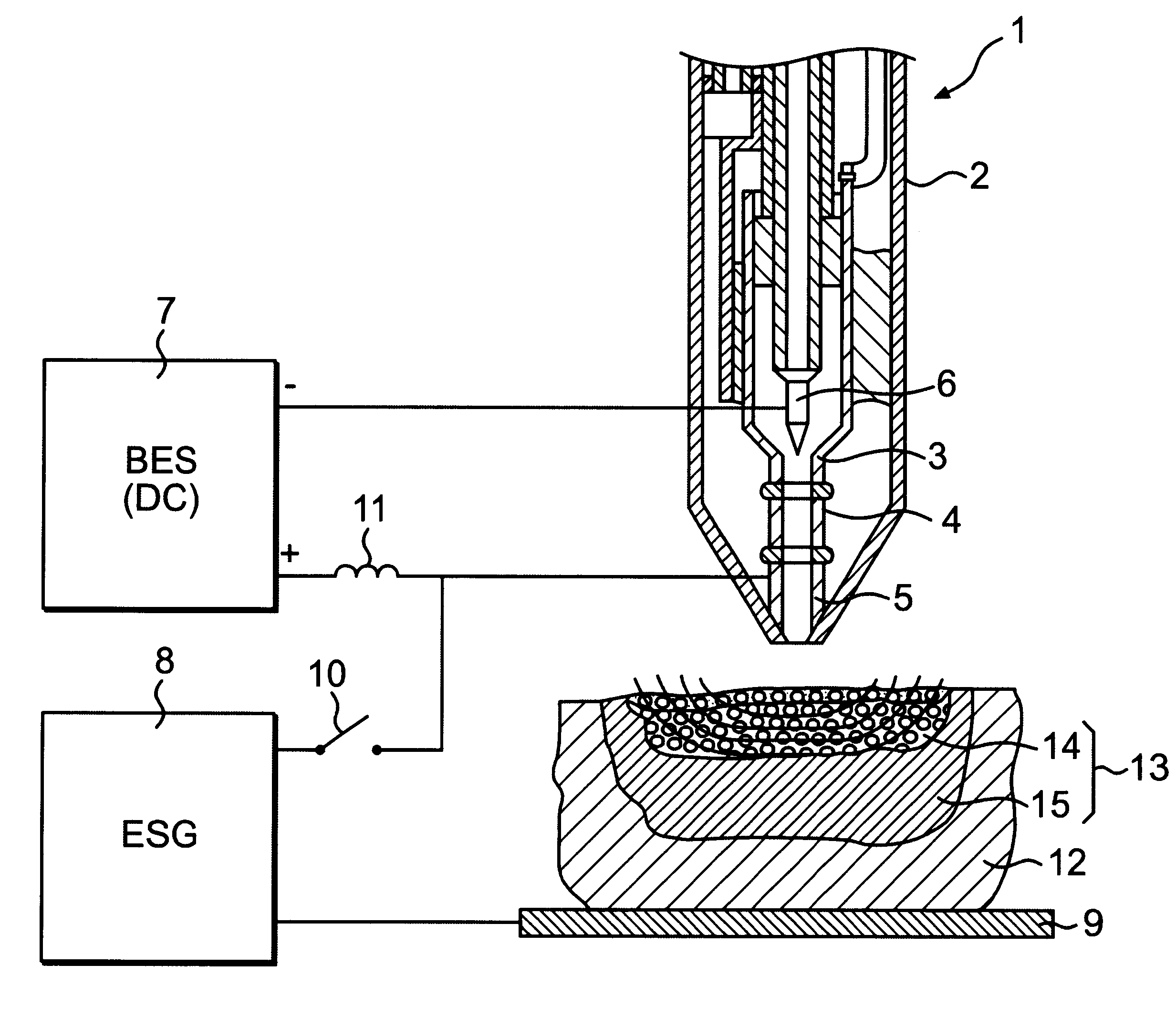
The above device is used according to the inventive method, which comprises the steps of generating the plasma flow and directing it towards a bleeding tissue, whereby a necrotic layer comprising a porous and a compact layer forms in the bleeding tissue. Electric high-frequency energy is transferred to the tissue through an electric circuit which comprises the plasma jet and the tissue, the electric energy being conducted through the plasma jet to the fluid limit of the tissue for increasing the thickness of the compact necrotic layer.
Advantageously, an electric switch is arranged for manually switching on and off the electrosurgical generator. It is then possible to use a method where electric high-frequency energy is supplied instantaneously to stop especially heavy bleedings in the tissue, for instance, in thick blood-vessels. In this case the electrosurgical function is used only when necessary. The plasma function is sufficient on most of the wound surfaces. Thus, the device and the method will be flexible and easy to use in connection with different types of surgery.

Problems solved by technology

The problem is made worse by the low heat conductivity of the porous layer.
However, in connection with very heavy bleedings, such as from thick blood vessels within, for instance, the liver, the blood stopping capacity is insufficient.
The formed necrotic layer is compact and relatively thin, and therefore, this technique can only be used in connection with small, capillary bleedings.
Because of the influence of the sparks and the electric arcs, the porous layer is, however, formed with depressions and is more porous, and thus also brittler than desired.
This current causes an unintentional excitation of nerves and muscles.
Another disadvantage is that relatively high voltages (2000 V) are required to obtain a satisfying effect.
The use of the method is limited to middle-sized bleedings owing to, inter alia, the previously mentioned problem caused by the insufficient heat conductivity and sublimation of the porous layer.

Method used


Image

  • Plasma knife
  • Plasma knife

Examples


Embodiment Construction

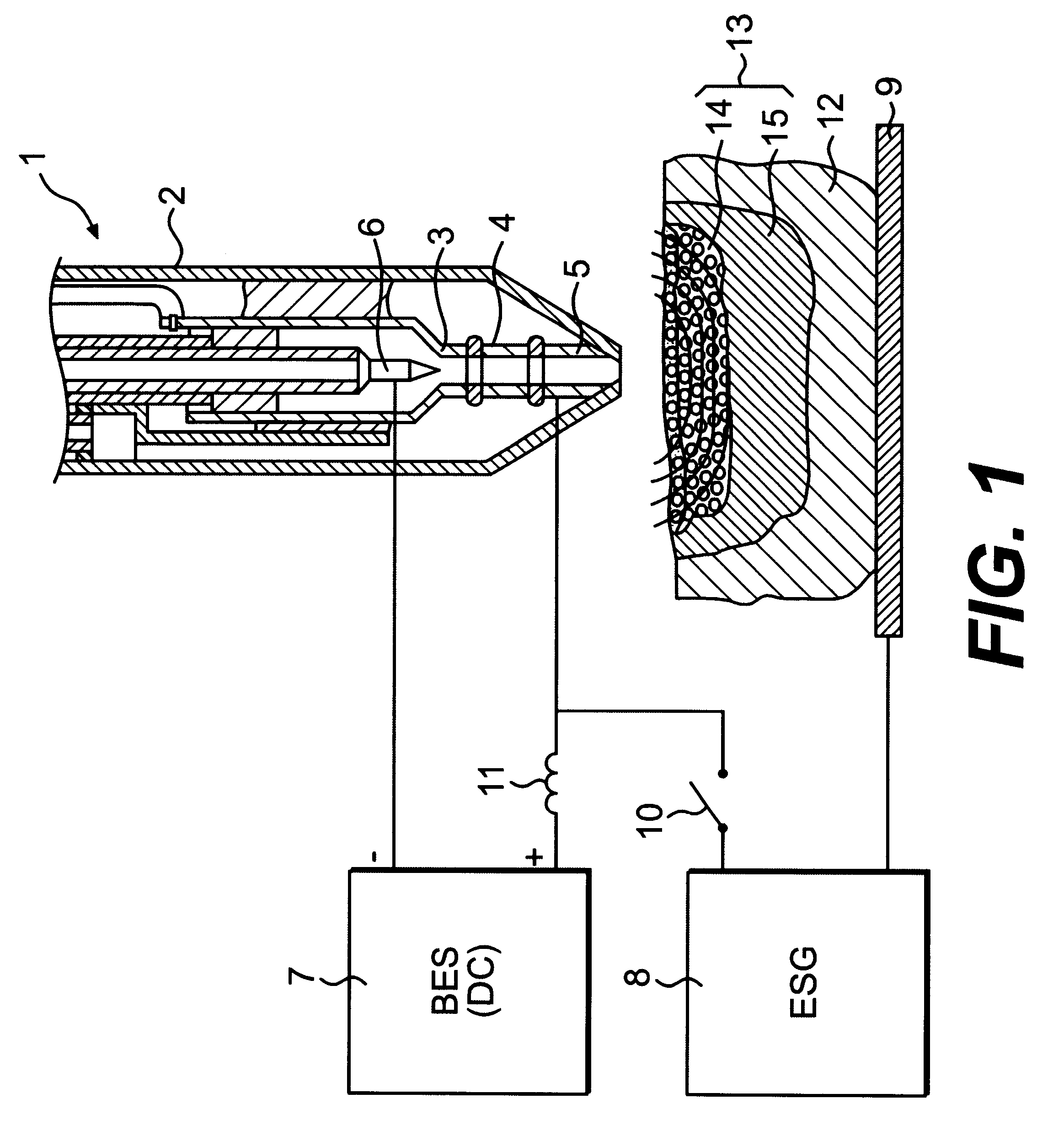
FIG. 1 shows a plasma-generating means 1 consisting of an electrically non-conductive body 2, which has the form of a pen. The body 2 has a cylindrical duct intended for heating a plasma-generating gas. The duct is formed of sections 3, 4, 5, which are electrically insulated from each other. At the inner end of the duct there is a cathode 6, which is connected to the negative pole of a basic energy source 7 (BES). The outer section 5 of the duct is connected to the positive pole of the basic energy source 7.

The means for transferring electric energy consists of an electrosurgical generator 8 (ESG), one pole of which is connected to the outer section 5 of the duct, and the other pole of which is connected to a diathermic plate 9, which is placed in contact with the patient. The circuit in which the electrosurgical generator is included is provided with an electric switch 16 for switching on and off the electrosurgical function. The electric switch can be operated by the surgeon. This...


PUM

PropertyMeasurementUnit
diameteraaaaaaaaaa
diameteraaaaaaaaaa
voltageaaaaaaaaaa

Abstract

A device for stopping a bleeding in living tissue in humans and animals by forming a necrotic layer in the tissue comprises a member for generating a dynamic plasma flow capable of wholly or partially penetrating an outer, porous layer of the necrotic layer. The device also has an electrosurgical generator arranged to transfer electric energy to the inner limit of the porous layer through a circuit that comprises the plasma flow and the tissue.

Description

The present invention relates to a device for stopping a bleeding in living tissue in humans and animals by forming a necrotic layer in the tissue, the device comprising a means for generating a dynamic plasma flow of such a character that it is capable of wholly or partially penetrating an outer, porous layer of the necrotic layer.The invention also relates to a method for use of such a device.TECHNICAL BACKGROUNDOne way of stopping bleedings in connection with surgery is by forming a necrotic layer (death of living tissue) on the bleeding tissue. Today a plurality of methods are available to form such a layer, inter alia, treatments with a plasma jet, laser irradiation, or electrosurgery. A common feature of all these methods is that a bleeding tissue is supplied with energy, forming a necrotic layer on the surface of the wound, which stops the bleeding. The necrotic layer usually consists of several layers. On the outside a porous necrotic layer forms, where the fluid component o...

Claims


Application Information

Patent Timeline
Patent Type & Authority Patents(United States)
IPC IPC(8): A61B18/00A61B17/32
CPCA61B18/042
Inventor SUSLOV, NIKOLAJ
Owner NIKVAL INT
Why Eureka
Try Eureka