Method and apparatus for etching silicon

a technology of etching and silicon, applied in electrical devices, decorative surface effects, decorative arts, etc., can solve the problems of etching treatment considerably expensive, etching back side of silicon wafer roughening, and etchant brown, etc., and achieve the effect of reducing the etching quality of silicon

Inactive Publication Date: 2002-09-03
DISCO CORP +1
View PDF7 Cites 16 Cited by
  • Summary
  • Abstract
  • Description
  • Claims
  • Application Information

AI Technical Summary

Problems solved by technology

However, the repeated use of the etchant tends to turn the etchant brown and roughen the etched back side of the silicon wafer.
This makes etching treatmen...

Method used


Image

  • Method and apparatus for etching silicon
  • Method and apparatus for etching silicon
  • Method and apparatus for etching silicon

Examples


Embodiment Construction

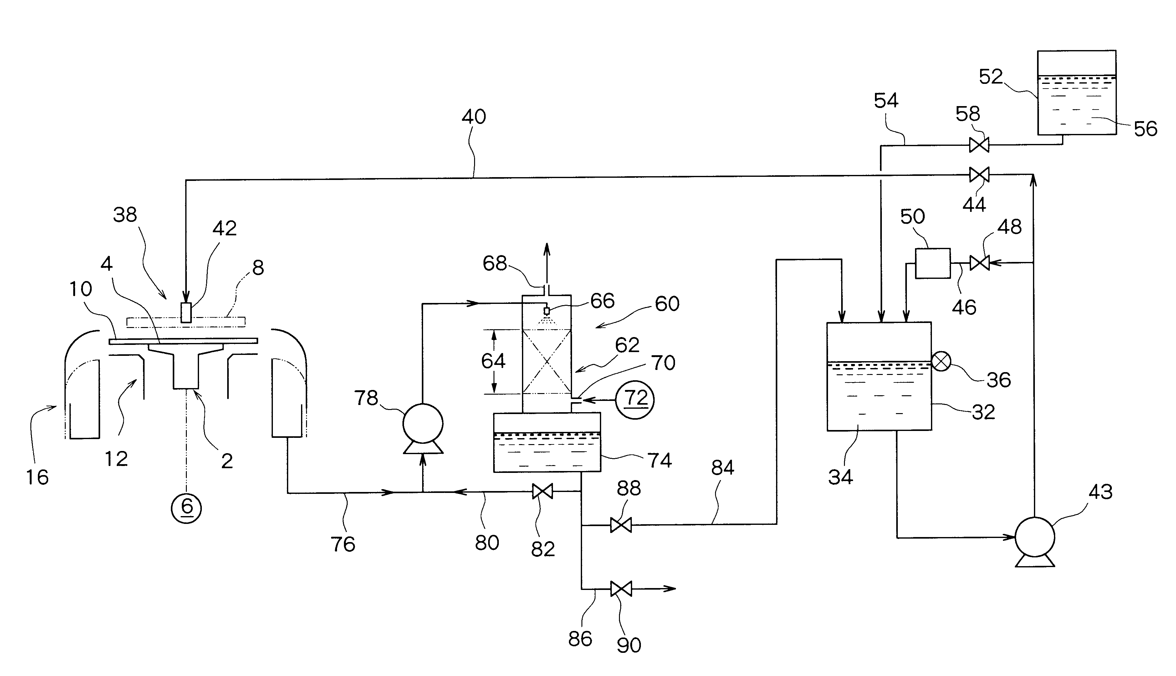
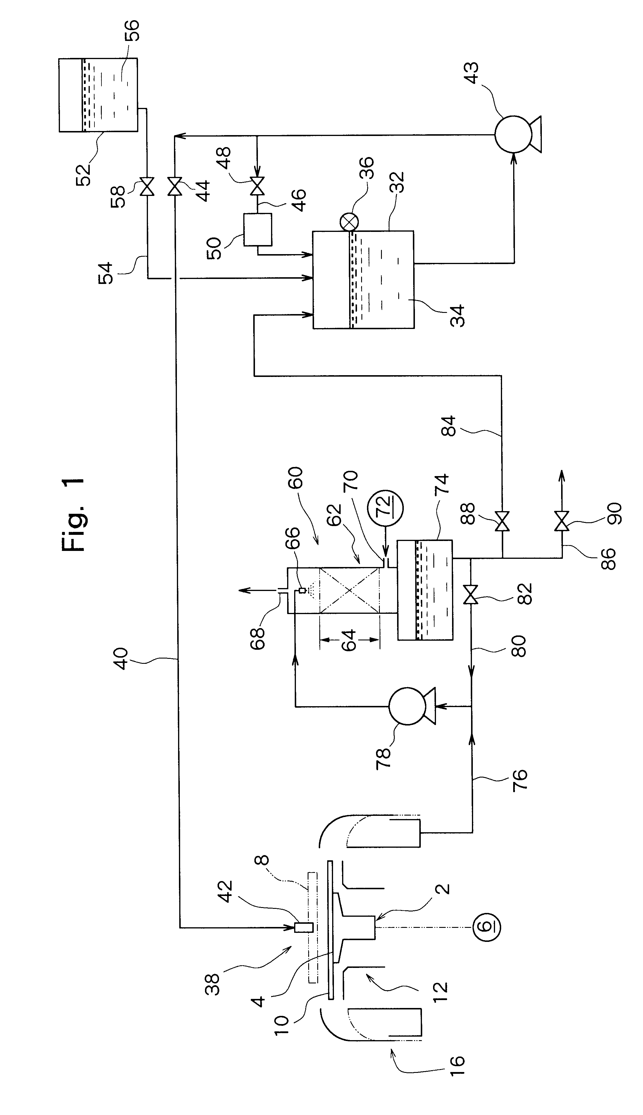
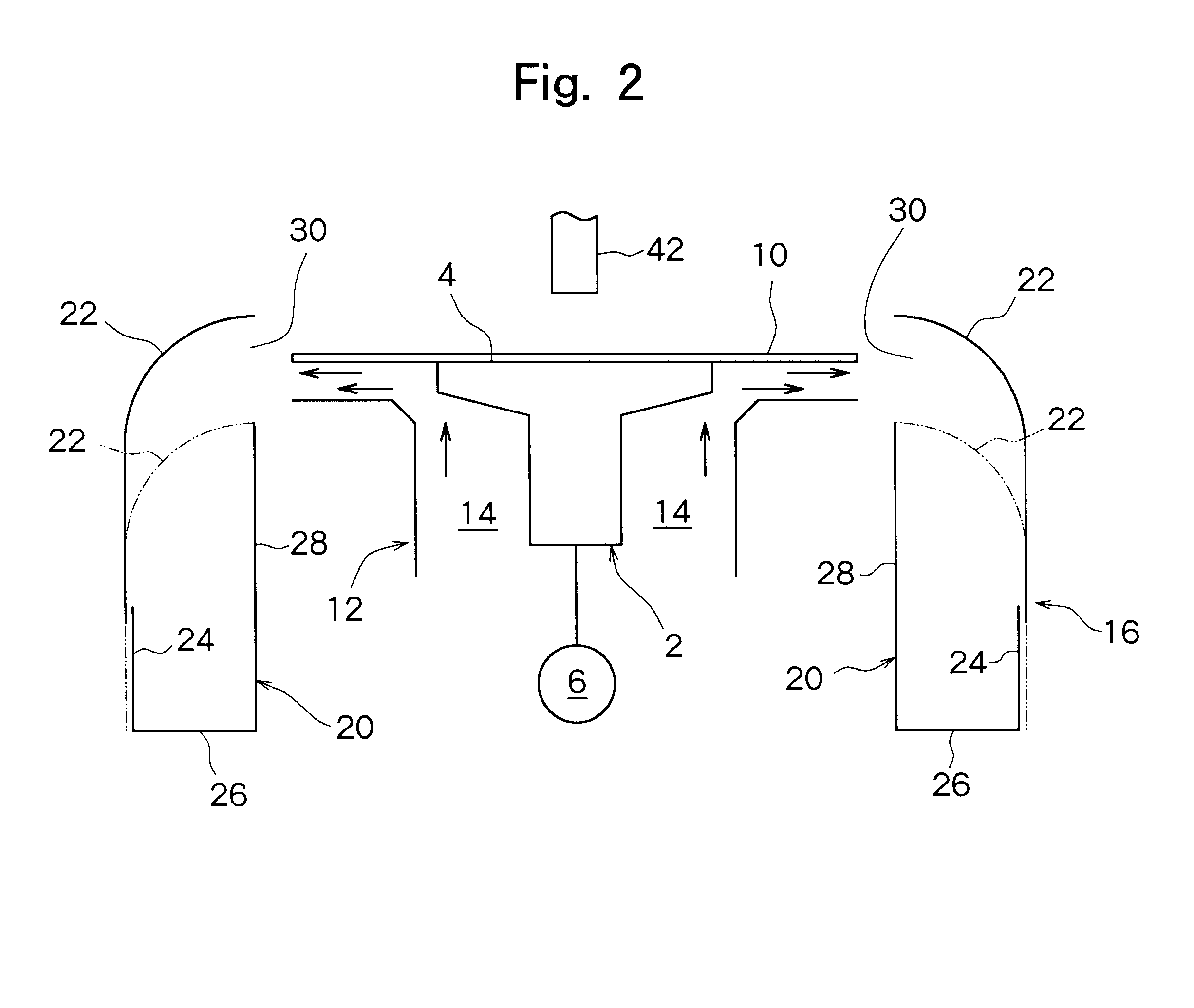
ground back side of a silicon wafer with a nominal diameter of 8 inches was etched with the use of the etching apparatus as explained with reference to FIGS. 1 and 2. Prior to the start of etching, 20 liters of an etchant was accommodated in the circulation tank. The etchant was an aqueous solution containing 59% by weight of nitric acid and 7% by weight of hydrofluoric acid. The level sensor provided on the circulation tank was set so as to detect the liquid level of the etchant when the etchant in the circulation tank amounted to 20 liters. The etchant in the circulation tank was circulated through the branch path on which the temperature adjustment means was disposed, to make the temperature of the etchant about 20.degree. C. Then, with the support means rotated at a speed of 600 rpm, the etchant was sprayed from the spray nozzle toward a central area of the upper surface of the silicon wafer on the support means to etch the upper surface, i.e., the back side, of the silicon wafe...


PUM

PropertyMeasurementUnit
Temperatureaaaaaaaaaa

Abstract

An etching method and an etching apparatus for applying an etchant containing nitric acid and hydrofluoric acid to silicon to etch the silicon. The etchant used in etching is recovered, and brought into contact with a gas inert to the etchant, whereby the etchant is regenerated. At least a part of the regenerated etchant is reused in etching.

Description

This invention relates to a method and an apparatus for etching silicon by applying an etchant containing nitric acid and hydrofluoric acid to the silicon.DESCRIPTION OF THE PRIOR ARTFor the production of a semiconductor device, it is well known to form circuits in many areas arranged in a lattice pattern on the surface of a silicon wafer, and dice the silicon wafer to separate the individual areas, thereby producing semiconductor chips. Before dicing the silicon wafer, it is common practice to grind the entire area of the back side of the silicon wafer for the purpose of improving heat dissipation of the resulting semiconductor chips and / or making them thin slices, and then etch the entire area of the back side of the silicon wafer, thereby removing strains caused by grinding. Etching is performed by applying an etchant containing nitric acid and hydrofluoric acid to the back side of the silicon wafer.When the back side of the silicon wafer is etched with a fresh etchant, the back ...

Claims


Application Information

Patent Timeline
IPC IPC(8): H01L21/02H01L21/306H01L21/00
CPCH01L21/02019H01L21/30604H01L21/67075H01L21/6708H01L21/306
Inventor YONEYA, AKIRAKOBAYASHI, NORIYUKIIZUTA, NOBUHIKO
Owner DISCO CORP
Why Eureka
Try Eureka