

Method and apparatus for improved luminescence assays using particle concentration chemiluminescence detection
a luminescence assay and particle concentration technology, applied in the direction of instruments, assay labels, material analysis by optical means, etc., can solve the problem that it has not appeared possible to use microparticulate matter in the measurement of luminescent phenomena, and achieve faster assay time, improved sensitivity, and greater sensitivity
- Summary
- Abstract
- Description
- Claims
- Application Information
AI Technical Summary
Benefits of technology
Problems solved by technology
Method used
Image

Examples
third embodiment
In a third embodiment, the particles may be removed by filtration from the assay composition. In this embodiment the particles need not have a density greater than the balance of the assay composition. The invention, the particles are separated from the solution and concentrated by drawing the solution through a filter, e.g. pumping and collecting the particles on the surface of the filter.
In a preferred embodiment, the suspended particles are magnetically responsive, e.g. they may be paramagnetic or ferromagnetic, and are collected in a measurement zone by imposition of a magnetic field on the particles. The measurement cell is equipped with a magnet. The magnetic field of the magnet applies a force on the particles as they reside in a batch cell or as they flow through a flow cell, causing them to separate from the bulk of the solution onto the surface of the cell which is in closest proximity to the magnet.
Several different heterogeneous and homogeneous formats for binding assays...
example 1
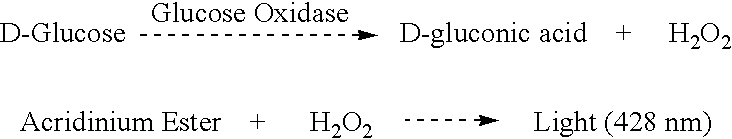
Chemiluminescent Apparatus and Method for Deposition of Microparticles
Magnetic Collection using a Sedimentation Cell
A cell for conduct of an assay using magnetic force to cause the microparticulate to settle is shown in FIG. 5. Reference numeral 21 refers to a transparent window, reference numeral 22 to a gasket, reference numeral 23 to the inlet in the cell block, reference numeral 25 to the sample outlet, reference numeral 26 to the cell block itself and reference 27 to an electromagnet.
The plane of the cell block is oriented horizontally. Labeled microparticles (Dynal) in buffer are drawn to the cell by means of a peristaltic pump. The pump is turned off after the microparticles reach the cell. The microparticles in the cell chamber are drawn to the collection zone by means of a magnetic field generated using electromagnet 27 operating at 12 volts and 1.5 amps. By application of the electromagnet, the rate of deposition of microparticles is greatly increased over that observed wh...
example 2
Chemiluminescent Apparatus and Method for Deposition of Microparticles
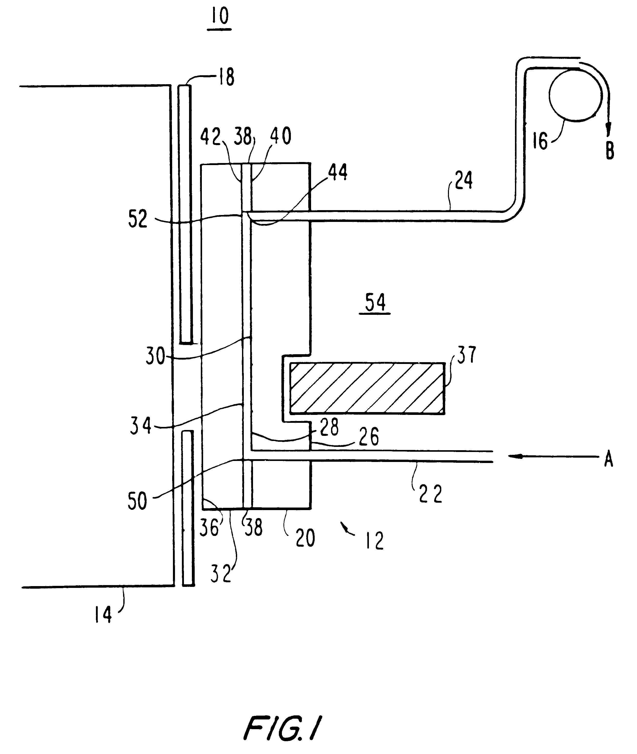
Magnetic Collection using a Collection Cell
An assay is carried out in a cell as described in FIG. 1. With reference to FIG. 1, reference numeral 32 refers to transparent window, reference numeral 38 to a gasket, reference numeral 22 to an inlet in the cell block, reference numeral 20 to the cell block itself, reference numeral 24 to the sample outlet and reference numeral 37 to a permanent magnet.
The plane of the cell block is oriented horizontally. Labeled microparticles (Dynal) in buffer are drawn to the cell by means of a peristaltic pump 11. Prior to the sample introduction, permanent magnet 37 is positioned immediately below the collection zone at a distance of 0.035 inches. As the sample is being drawn to the cell, the microparticles collect in a collection zone, as defined by the area of the magnet. The pump is turned off. The longer the collection time, the more particles are collected.
PUM
| Property | Measurement | Unit |
|---|---|---|
| density | aaaaa | aaaaa |
| density | aaaaa | aaaaa |
| size | aaaaa | aaaaa |
Abstract
Description
Claims
Application Information