Differential transmission cable and joint with specific distances

a transmission cable and specific distance technology, applied in the direction of cable, line-transmission details, coupling device connections, etc., can solve the problems of radiation noise, noise current, radiation noise generation,

Inactive Publication Date: 2002-09-10
HITACHI METALS LTD
View PDF8 Cites 38 Cited by
  • Summary
  • Abstract
  • Description
  • Claims
  • Application Information

AI Technical Summary

Benefits of technology

Accordingly, an object of the present invention is to provide an inexpensive, highly reliable, differential transmission cable capable of dramatically attenuating radiation noise while fully keeping the quality of digital signal waveform, and a joint for connecting such a differential transmission cable to a device.

Problems solved by technology

However, actual differential transmission cables are likely to generate radiation noise.
One of the causes therefor is that noise current and thus radiation noise are generated by the uncancelled difference between a pair of digital signals that is caused by the destroyed balance of the differential transmission signals.
Another cause is that conduction noise generated from personal computers and peripheral devices flow through the transmission cables, generating radiation noise.
However, the above conventional differential transmission cable attenuates high-frequency components in digital signals, resulting in the deformation of the digital waveform.
On the other hand, if the quality of the digital signal is to be kept, only insufficient attenuation would be obtained in radiation noise.
The above conventional technology is thus unsatisfactory in suppressing radiation noise while keeping the quality of the digital signal waveform.

Method used


Image

  • Differential transmission cable and joint with specific distances
  • Differential transmission cable and joint with specific distances
  • Differential transmission cable and joint with specific distances

Examples


example 2

Constitution of Connector

FIG. 9 shows a connector (series-A connector for USB cable) in a differential transmission cable, in which a transmission transformer was mounted. FIG. 10 shows a substrate used in FIG. 9, and FIG. 11 shows another example of a substrate.

In this EXAMPLE, a common-mode choke coil 4, one type of a transmission transformer, was mounted to lands 21 of a substrate 11a, and signal lines 5 and lead lines 12 of the USB cable 3 were connected to the lands 21 of the substrate 11a by soldering. With the lands 21, high reliability was achieved in soldering connection strength of the signal lines 5 and the lead lines 12 to the lands 21, and in soldering connection strength of the lands 21 to the common-mode choke coil 4.

By integrally resin-molding the substrate 11a provided with the cable 3 and the common-mode choke coil 4 except for tip portions of electric power lines 14 and lead lines 12, mechanical and electrical reliability can be improved. In this case, because the...

example 3

Other examples of connectors in the differential transmission cable of the present invention are shown in FIGS. 13 to 16. FIG. 13 shows a housing for a series-A connector of a USB cable. The housing 7b in this EXAMPLE is provided with a positioning projection holder 25a in a site 24 to which a common-mode choke coil is mounted, to prevent defects due to the displacement of the common-mode choke coil at the time of mounting. As long as the positioning projection holder 25a can secure a site into which the common-mode choke coil is inserted, it may have any shape. For instance, if it is in a shape having a hook 25b in an upper portion as shown in FIG. 14, defects due to the displacement of the common-mode choke coil at the time of mounting can drastically be suppressed. Incidentally, the holders 25a, 25b are preferably formed at the time of forming the housing.

After mounting connector terminals 15, 6a to this housing, the common-mode choke coil 4 is mounted to the housing, and signal ...

example 4

Evaluation of Joint

FIG. 17 shows one example of a joint used for connecting a cable to a personal computer. A common-mode choke coil 4 is mounted to a substrate 11a on a female connector 60b, and terminals 6a, 15 of a series-A male connector 60a are soldered to the terminals 6b, 16 of the female connector 60b and the substrate 11a via lead lines 17. With this structure, high reliability in soldering is secured between the lead lines 17 and the common-mode choke coil 4. Next, the male connector 60a, the female connector 60b and the substrate 11a are integrally resin-molded, to assemble a joint with parts such as shield plates, etc. Because the substrate 11a provided with the common-mode choke coil 4 is embedded in a molding portion 13, high reliability is achieved. Further, because housings 7a, 7c of commercially available connectors may be used without modifications, there is no need to produce a special connector for mounting a common-mode choke coil 4 into the joint.

To evaluate th...


PUM

PropertyMeasurementUnit
distanceaaaaaaaaaa
distanceaaaaaaaaaa
lengthaaaaaaaaaa

Abstract

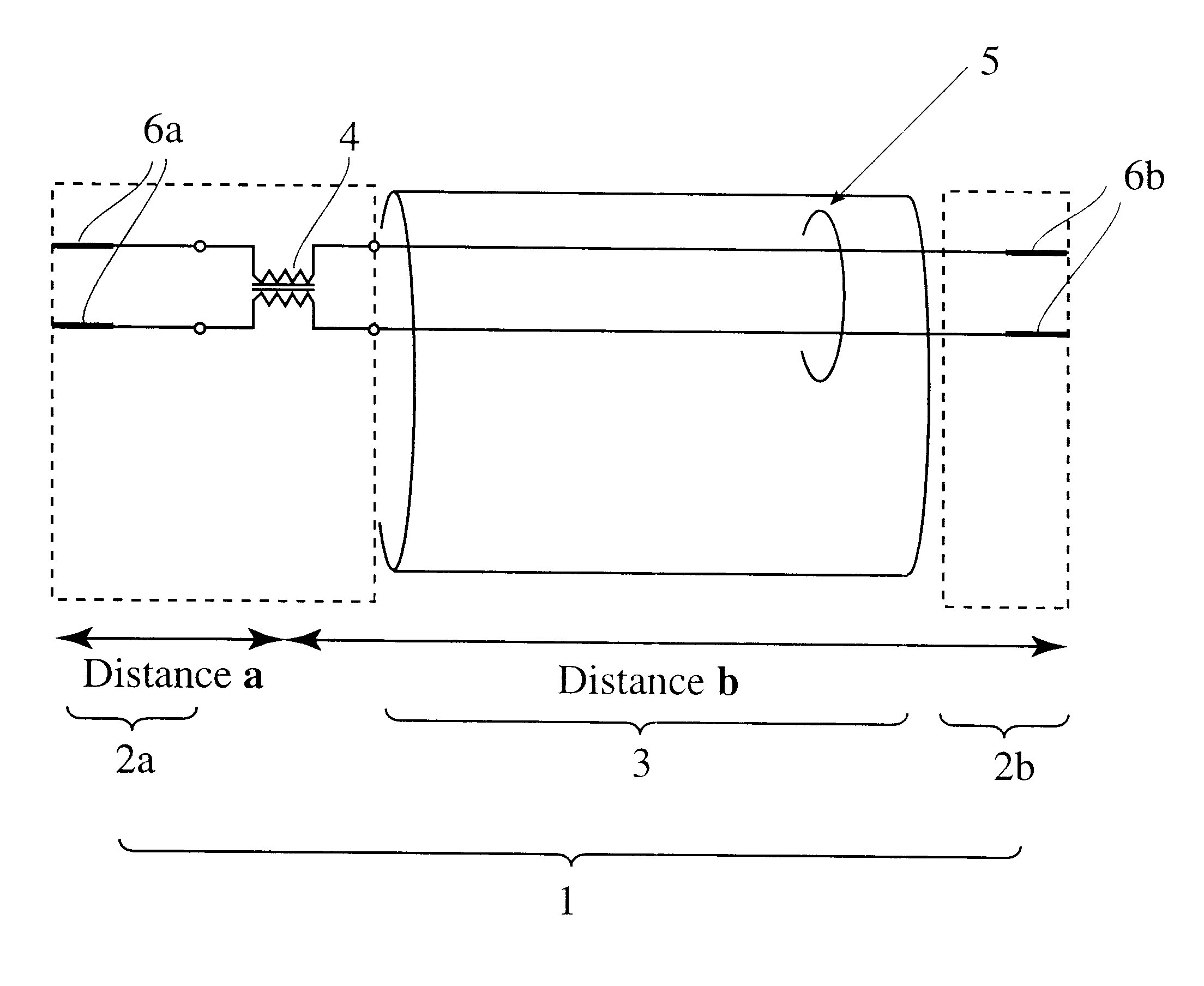
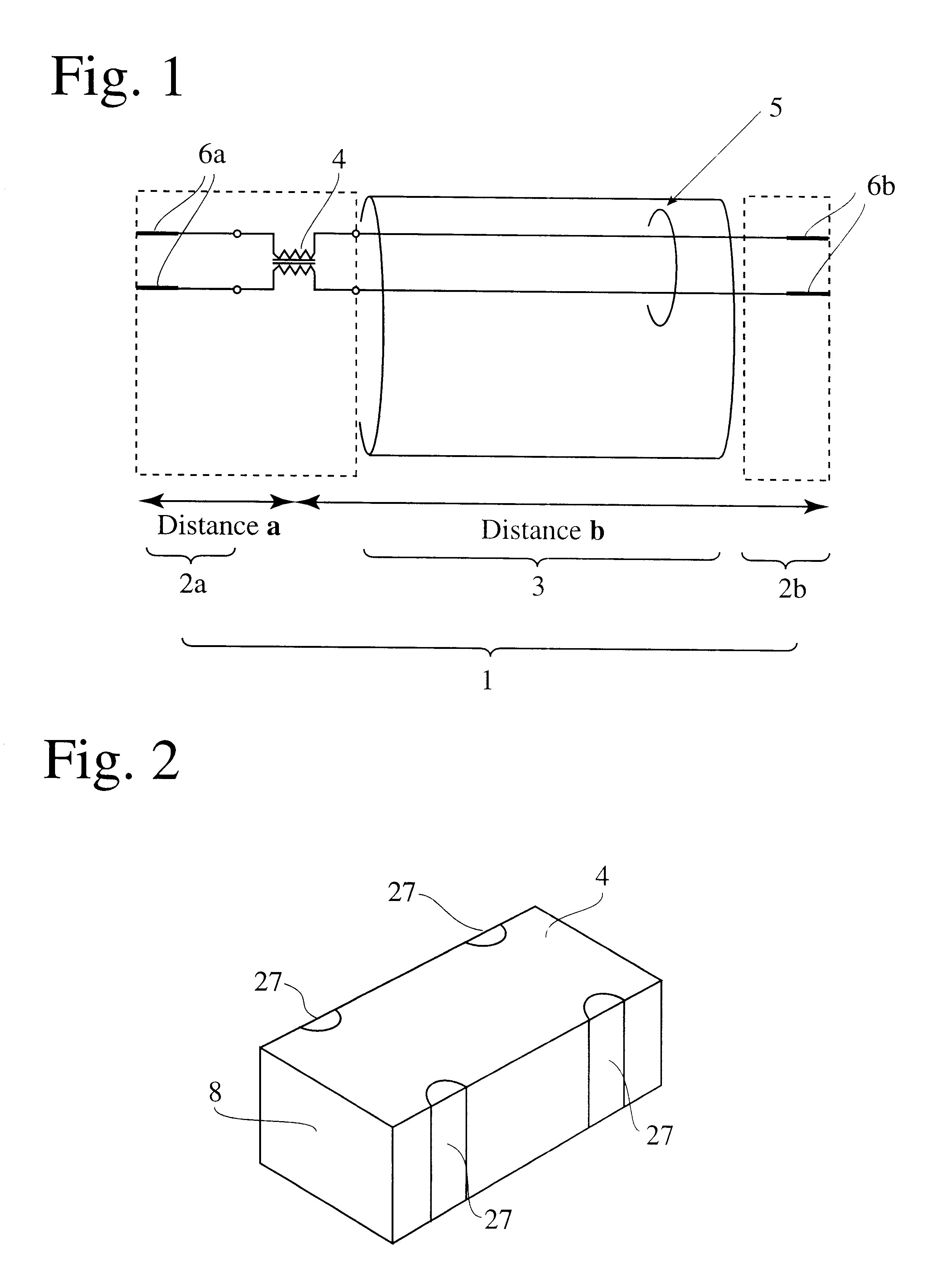
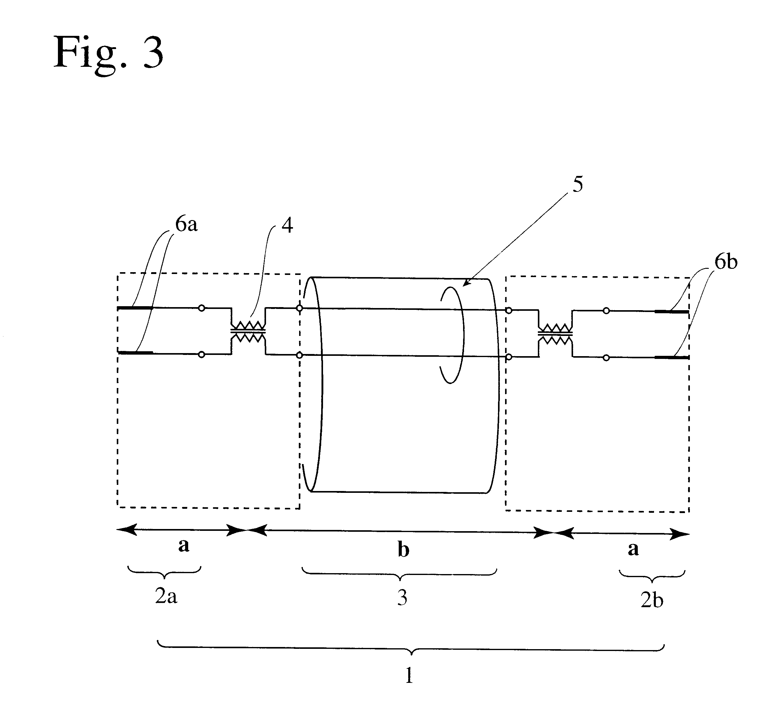
The differential transmission cable comprises a cable having at least one pair of differential transmission lines, one or more transmission transformers, and connectors at both ends, the transmission transformer having an integrally sintered laminate structure and a coupling coefficient of 0.65 to 0.98 at 100 MHz, the distance between a center of the transmission transformer and a tip end of the closest connector being within 0.1 m, and the distance between a center of the transmission transformer and a tip end of the farthest connector or between a center of the transmission transformer and a center of the other transmission transformer being 0.5 to 4 m. The transmission transformer is mounted onto a substrate, which is inserted into the connector or a housing of the connector having lands or a positioning holder. After wiring, the connector including the substrate is integrally resin-molded.

Description

The present invention relates to a differential transmission cable capable of suppressing radiation noise and a joint for connecting such a differential transmission cable to a device.DESCRIPTION OF PRIOR ARTThe differential transmission cable is a transmission cable for use in a differential transmission system, which is a digital transmission system for sending digital signals in apposite directions through a pair of lines with or without bias. Seeing the lines of the differential transmission system from far, high-frequency components are theoretically cancelled, emitting no radiation noise. Accordingly, the differential transmission system is put into practical use to send digital signals between computers and their peripheral devices. The transmission standards of digital signals transmitted through differential transmission cables include a universal serial bus (USB), IEEE1394, etc.Because outside noise conveyed in the air are equivalently induced in a pair of lines, there is ...

Claims


Application Information

Patent Timeline
Patent Type & Authority Patents(United States)
IPC IPC(8): H01B11/16H01B11/02H04B3/34H04B3/02
CPCH01B11/16H04B3/34
Inventor OGAWA, TOMOMINISHIYAMA, TOSHIKAZUARAKI, HIROKAZUOKADA, KATSUHIROTANI, YASUOIKEMOTO, OSAMU
Owner HITACHI METALS LTD
Why Eureka
Try Eureka