Liquid crystal display device

a display device and liquid crystal technology, applied in static indicating devices, non-linear optics, instruments, etc., can solve the problems of high-speed writing operation of one pel line, high cost of high-speed liquid crystal materials, and high cost of high-speed drivers

Inactive Publication Date: 2002-09-10
LENOVO (SINGAPORE) PTE LTD
View PDF9 Cites 249 Cited by
  • Summary
  • Abstract
  • Description
  • Claims
  • Application Information

AI Technical Summary

Problems solved by technology

Such a high speed writing operation for one pel line can not be achieved by a currently available thin film transistor (TFT) that is made of an amorphous semiconductor and ...

Method used


Image

  • Liquid crystal display device
  • Liquid crystal display device
  • Liquid crystal display device

Examples


first embodiment

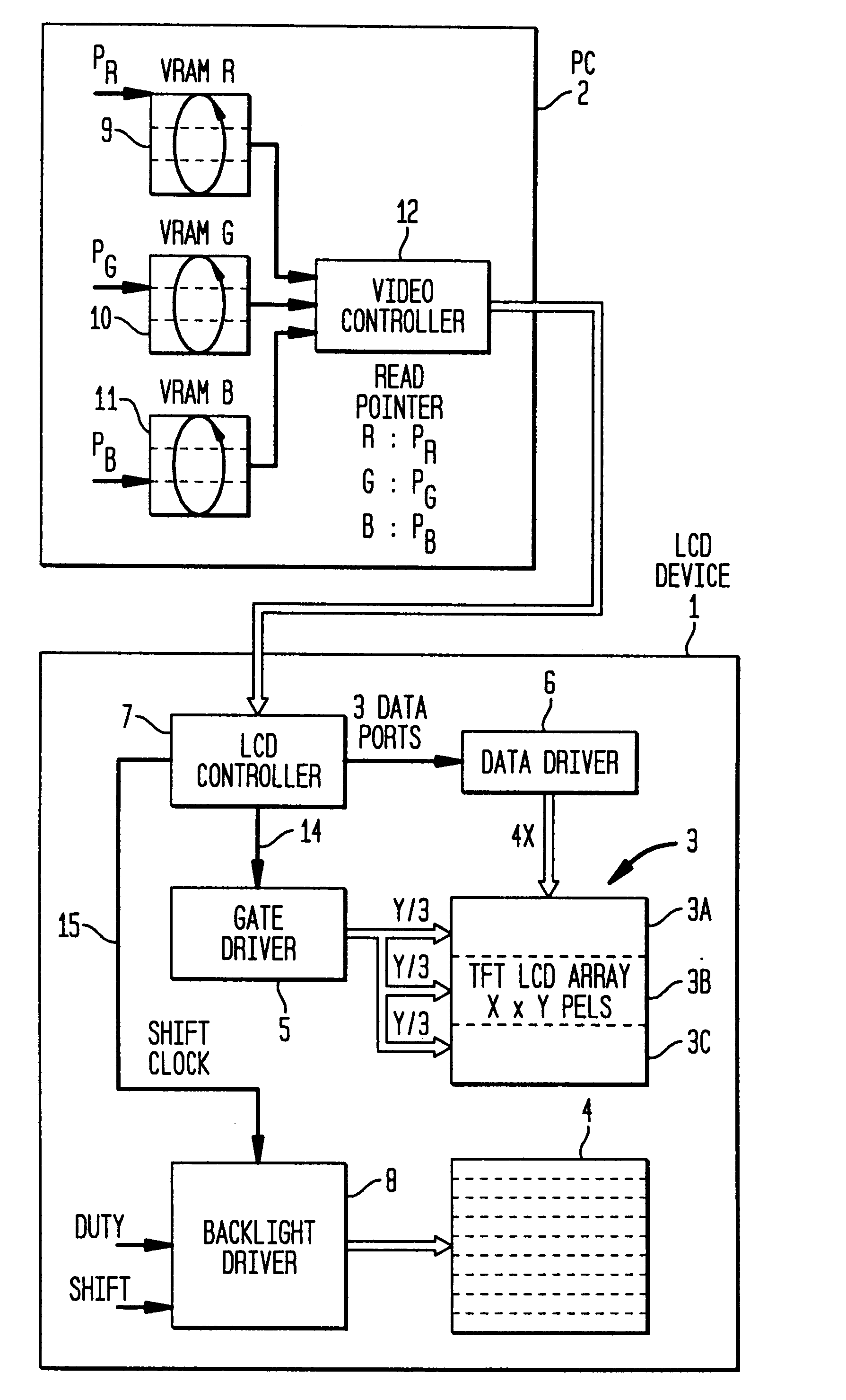
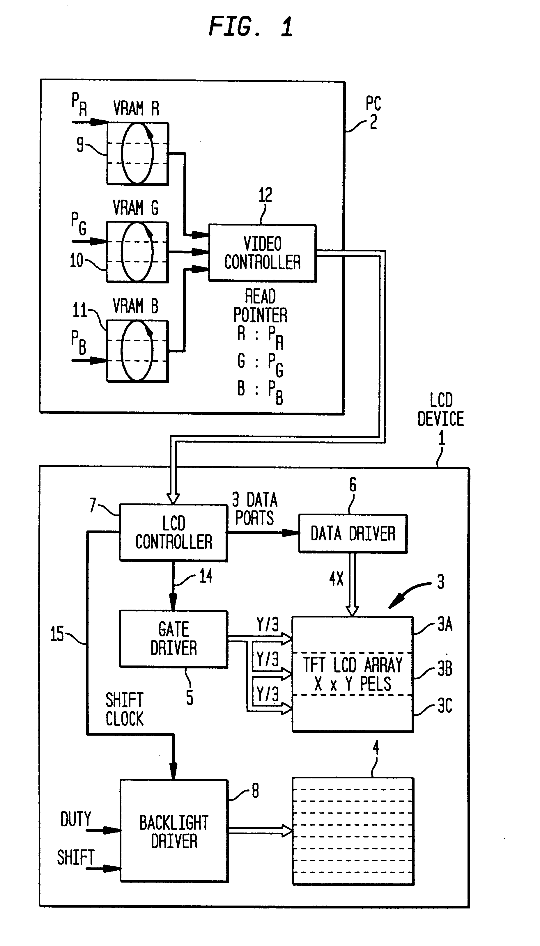
FIG. 1 is a block diagram illustrating a liquid crystal display device (LCD) 1 and a personal computer (PC) 2, which are employed for the screen division method according to the present invention. The LCD device 1 comprises: a thin film transistor (TFT) LCD array 3; a backlight 4; a gate driver 5; a data driver, i.e., a source driver 6; and LCD controller 7; and a backlight driver 8. According to the screen division method, the display screen of the TFT LCD array 3 is divided into three areas 3A, 3B and 3C.

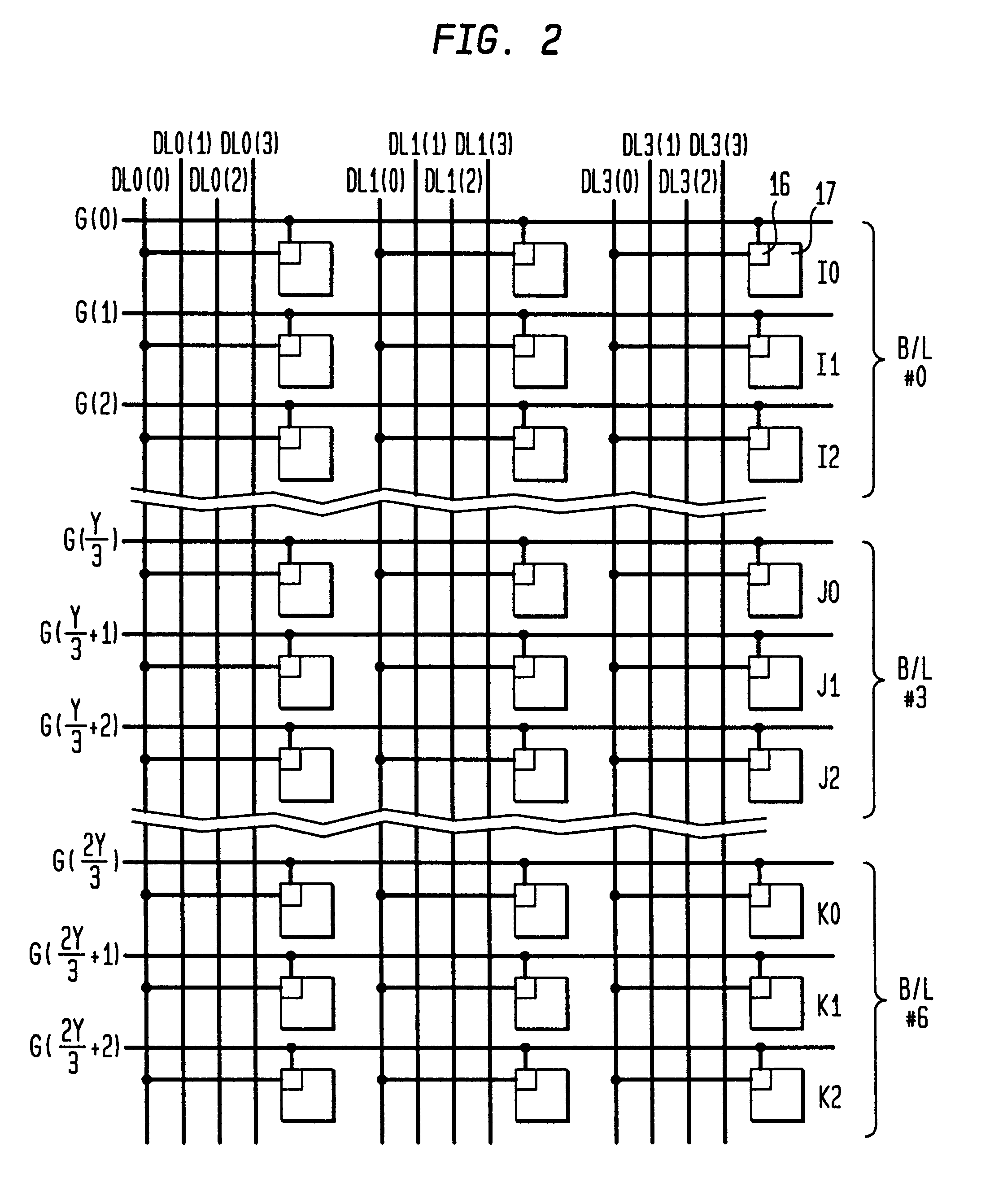
In FIG. 2 is shown one part of the TFT LCD array 3. A plurality of gate lines are horizontally provided in the TFT LCD array 3, and a plurality of data lines are vertically provided in the TFT LCD array 3. One TFT that constitutes one picture element, i.e., one pixel (pel), is connected at each of the intersections of the gate lines and the data lines. A plurality of pels that are connected to a single gate line are collectively called a pel line. More specifically, a gate electro...

second embodiment

In the screen division method, N is a multiple of 3. It should be noted that N is equal to or greater than 6 and is smaller than the total count of the pel lines in the TFT LCD array 3. The time division method employed for the second embodiment will be described later.

In FIG. 4 is shown the relationship between the backlight sections and the three areas 3A, 3B and 3C in the TFT LCD array 3. To simplify the screen illustration and the explanation, N=9 is employed in Table 1. The backlight sections #0, #1 and #2 are assigned for the first 1 / 3, area 3A, of the TFT LCD array 3; the backlight sections #3, #4 and #5 are assigned for the second 1 / 3, area 3B, of the TFT LCD array 3; and the backlight sections #6, #7 and #8 are assigned for the third 1 / 3, area 3C, of the TFT LCD array 3. The individual backlight sections each include a red (R) light-emitting diode (LED), a green (G) light-emitting diode (LED) and a blue (B) light-emitting diode (LED). The backlight driver 8 selectively acti...


PUM


Abstract

A low cost LCD device employing a high speed field sequential drive scheme. The liquid crystal display device comprises: a liquid crystal display array divided into a first area, a second area and a third area, in each of which are included a plurality of pel lines; a first device for performing an operation for sequentially writing first color data, selected from data provided for red, green and blue, along the plurality of pel lines in the first area, an operation for sequentially writing second color data, selected from data provided for red, green and blue, along the plurality of pel lines in the second area, and an operation for sequentially writing third color data, selected from data provided for red, green and blue, along the plurality of pel lines in the third area; a backlight device, which is divided into N backlight sections, with N being a multiple of three (3) and is equal to or greater than (6), and which selectively generates red light, green light or blue light, wherewith N/3 backlight sections illuminate the first area, N/3 backlight sections illuminate the second area and N/3 backlight sections illuminate the third area; and a second device for sequentially activating the N/3 backlight sections for the second area to generate second color light and sequentially displaying the second color data in the second area, and for sequentially activating the N/3 backlight sections for the third area to generate third color light and sequentially displaying the third color data in the third area.

Description

1. Technical FieldThe present invention relates to a liquid crystal display device that is driven in accordance with a field sequential drive scheme, and more specifically to a liquid crystal display device for which the high speed sequential drive scheme can be employed.2. Prior ArtA field sequential drive scheme has been employed to display a color image on a liquid crystal display (LCD) device without using a color filter. According to the field sequential drive scheme, image data for one color are written to an LCD panel, and when a response time required for switching the state of liquid crystal molecules has elapsed, a backlight for that color is turned in to display the image data. This repetitious operation is performed for red (R), green (G) and blue (B) colors. In order to provide a satisfactorily extended turn-On period for a backlight, a high speed writing circuit (high speed driver) and a high speed liquid crystal material are required. When the LCD panel is driven at a...

Claims


Application Information

Patent Timeline
IPC IPC(8): G09G3/36G09G3/34G02F1/1335G02F1/133G02F1/13357
CPCG09G3/3413G09G3/342G09G3/3666G02F2001/133622G09G3/3677G09G2310/0205G09G2310/0235G09G2310/024G02F1/133622
Inventor SAKAGUCHI, YOSHITAMIYAMADA, FUMIAKITAIRA, YOICHI
Owner LENOVO (SINGAPORE) PTE LTD
Why Eureka
Try Eureka