Electrical connectors adapted to reduce or prevent adherence of conductive material to contact portions as the connector

a technology of conductive material and connector, applied in the field of electric connector, can solve the problems of increasing the man-hour of operation, increasing the cost of operation, and and achieve the effect of reducing the adhesion of solder or oxide impurities

Inactive Publication Date: 2002-09-17
THE FUJIKURA CABLE WORKS LTD
View PDF5 Cites 20 Cited by
  • Summary
  • Abstract
  • Description
  • Claims
  • Application Information

AI Technical Summary

Benefits of technology

It is an object of the invention to provide an improved electrical connector which eliminates all the disadvantages of the prior art described above and which minimizes the adherence of solder or oxide impurities to treated surface layers of electric contact elements even after repeated contacts between electric contacts and the electric contact elements of first and second connectors more than several thousand times.

Problems solved by technology

However, the removal of the adhered solder by brushing is not an easy matter if not impossible.
In order to remove the adhered solder more completely, it is required to increase the times of the brushing operation, which also increases the man-hour of the operation of the electrical connector, resulting in increased cost of operation.

Method used


Image

  • Electrical connectors adapted to reduce or prevent adherence of conductive material to contact portions as the connector
  • Electrical connectors adapted to reduce or prevent adherence of conductive material to contact portions as the connector
  • Electrical connectors adapted to reduce or prevent adherence of conductive material to contact portions as the connector

Examples


Embodiment Construction

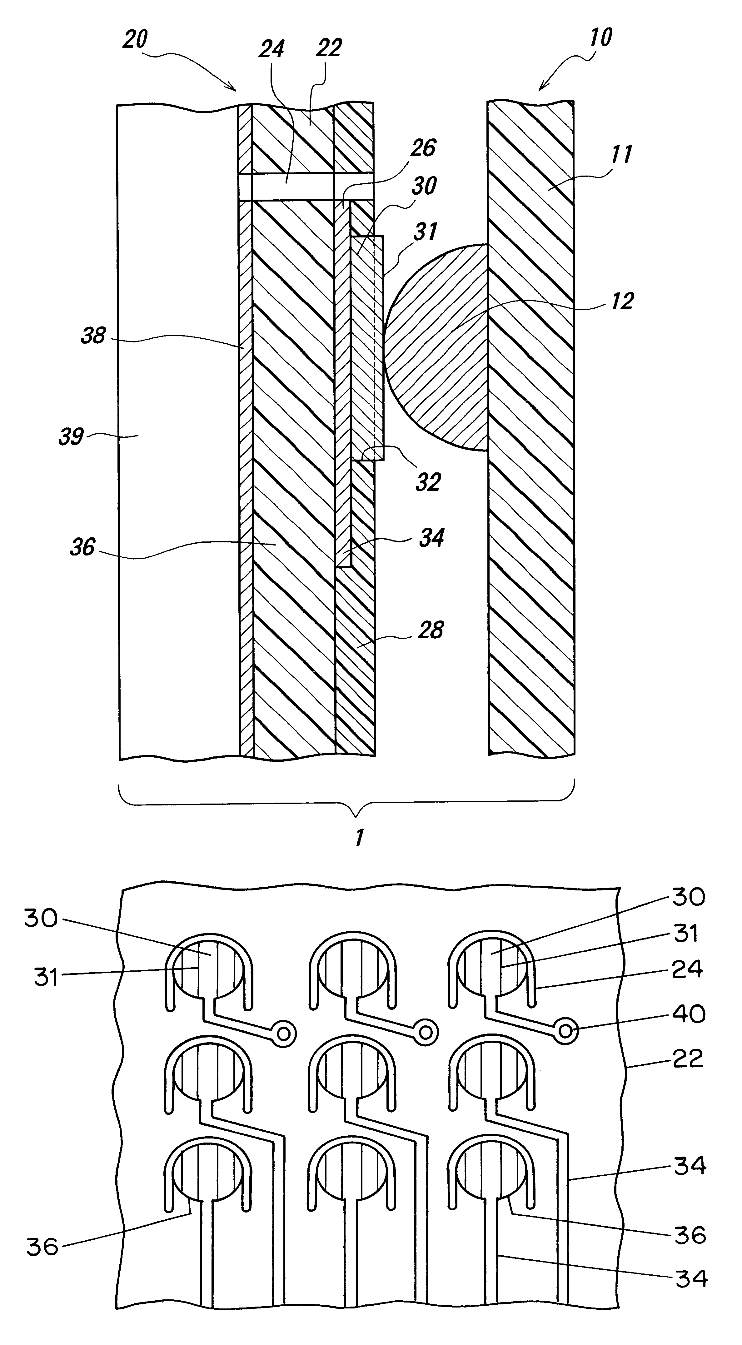
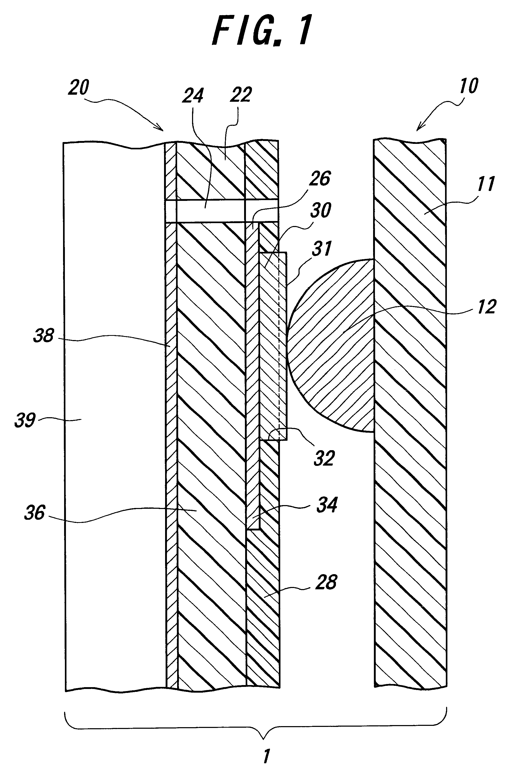
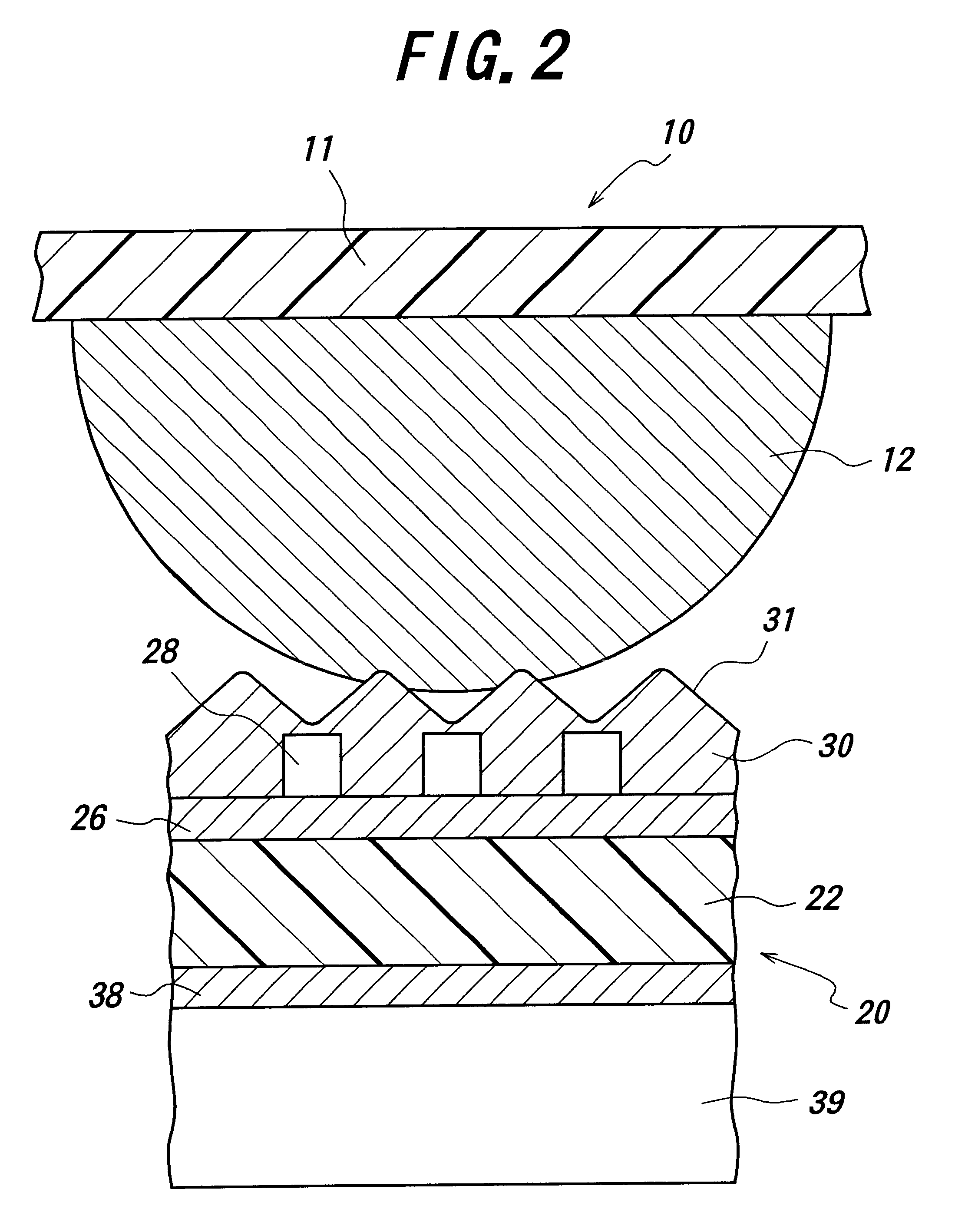
FIGS. 1 to 4 illustrate one preferred embodiment of the electrical connector 1 according to the invention. In the drawings, a first connector 10 includes a connector plate 11 made of a ceramic or hard resin substrate or board having a rigidity as in a conventional connector plate, and a plurality of electric contacts 12 of solder or the like in the form of hemispherical protrusions provided on one surface of the connector plate 11. A second connector 20 includes a connector plate or board 22 made of a soft resin or the like having an appropriate rigidity, a plurality of electric conductors 26 of disc-shaped metal layers on one surface of the board 22 facing to the electric contacts 12 of the first connector 10, a protection covering layer 28 of an insulating material provided on the board 22 on the same side as the electric conductors 26, a plurality of electric contact elements 30 provided on the electric conductors 26, and protrusions or ridges 31 in the form of a mountain range p...


PUM

PropertyMeasurementUnit
heightaaaaaaaaaa
elasticaaaaaaaaaa
conductiveaaaaaaaaaa

Abstract

An electrical connector includes a first connector having a connector plate and a plurality of electric contacts thereon, and a second connector having a plurality of electric contact elements provided on conductors arranged on a board. The board is formed with slits around the conductors to support the conductors elastically by parts of said board surrounded by the slits. The first and second connectors are brought into detachable abutment against each other to electrically connect to electric contacts and the electric contact elements of the first and second connectors. The electric contact elements of the second connector each are provided with at least one ridge, preferably plural ridges facing to the electric contact of the first connector. The ridges preferably extend in parallel with the direction of sliding movement of the electric contacts caused by the elastic support of the conductors. With this arrangement, after repeated connections between two connectors a great many times more than thousands, no foreign substance can adhere to the electric contact elements and no longer is there any incorrect electrical connection between the contacts.

Description

BACKGROUND OF THE INVENTIONThis invention relates to an electrical connector adapted to be able to electrically connect a plurality of electric contacts and a plurality of electric contact elements at a time, and more particularly to an electrical connector including first and second connectors adapted to prevent any solder of the first connector from adhering to contact portions of the second connector.We have ever proposed an electrical connector adapted to be able to electrically connect a plurality of electric contacts and electric contact elements at a time in U.S. patent application Ser. No. 09,366,832 filed Aug. 4, 1999, U.S. Pat. No. 6,220,871. The proposed electrical connector will be explained with reference to FIG. 6.Referring to FIG. 6, the electrical connector 60 includes a first connector 10 (Ball Grid Array or BGA) and a second connector 50 (which is a socket connector to be connected to BGA elements or the like). When the first and second connectors 10 and 50 are bro...

Claims


Application Information

Patent Timeline
Patent Type & Authority Patents(United States)
IPC IPC(8): H05K7/10H05K3/32H05K3/40C25D7/00H01R12/00C25D5/02H01R13/03H01R33/76H05K1/00
CPCH01R12/57H05K3/326H05K3/4007H05K7/1061H05K3/325H05K2201/0373H05K2201/09081
Inventor OTSUKI, TOMONARIYAMAZAKI, YASUE
Owner THE FUJIKURA CABLE WORKS LTD
Why Eureka
Try Eureka