Method, device, and system for evaluating characteristics of optical fiber transmission line

a technology of optical fiber transmission line and characteristics, applied in the direction of transmission monitoring, electromagnetic repeaters, instruments, etc., can solve the problems of transmission line breaking, difficulty in accurately grasping the mode field diameter of the optical fiber used, and the possibility of large errors, so as to achieve accurate evaluation of the characteristics of the optical fiber transmission line

Inactive Publication Date: 2002-09-17
FUJITSU LTD
View PDF18 Cites 20 Cited by
  • Summary
  • Abstract
  • Description
  • Claims
  • Application Information

AI Technical Summary

Benefits of technology

It is therefore an object of the present invention to provide a method, device, and sys

Problems solved by technology

It is difficult to accurately grasp the mode field diameter of an optical fiber used as an optical fiber transmission line from the viewpoint of a method of manufacturing .
Accordingly, in the case of evaluating the characteristics of an optical fiber transmission line, such as a loss at a splice connection point on the optical fiber transmission line, there is a possibility of large errors due to variations in gain

Method used


Image

  • Method, device, and system for evaluating characteristics of optical fiber transmission line
  • Method, device, and system for evaluating characteristics of optical fiber transmission line
  • Method, device, and system for evaluating characteristics of optical fiber transmission line

Examples


Embodiment Construction

Some preferred embodiments of the present invention will now be described in detail with reference to the attached drawings. Throughout the drawings, substantially the same parts are denoted by the same reference numerals.

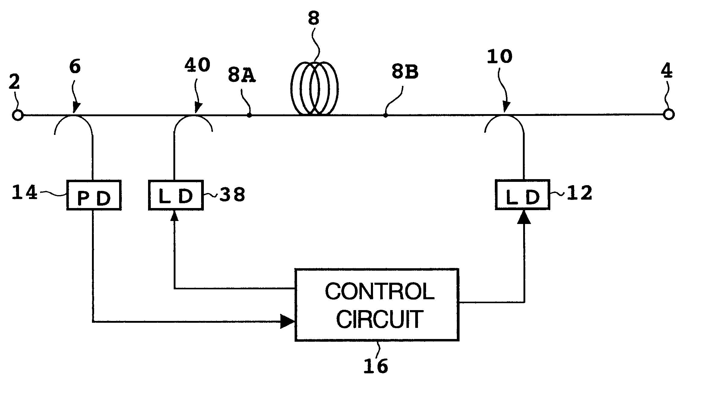
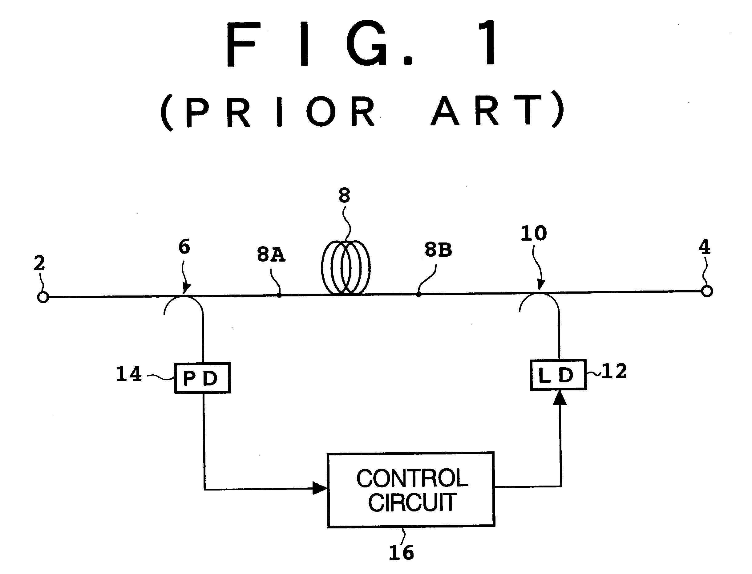
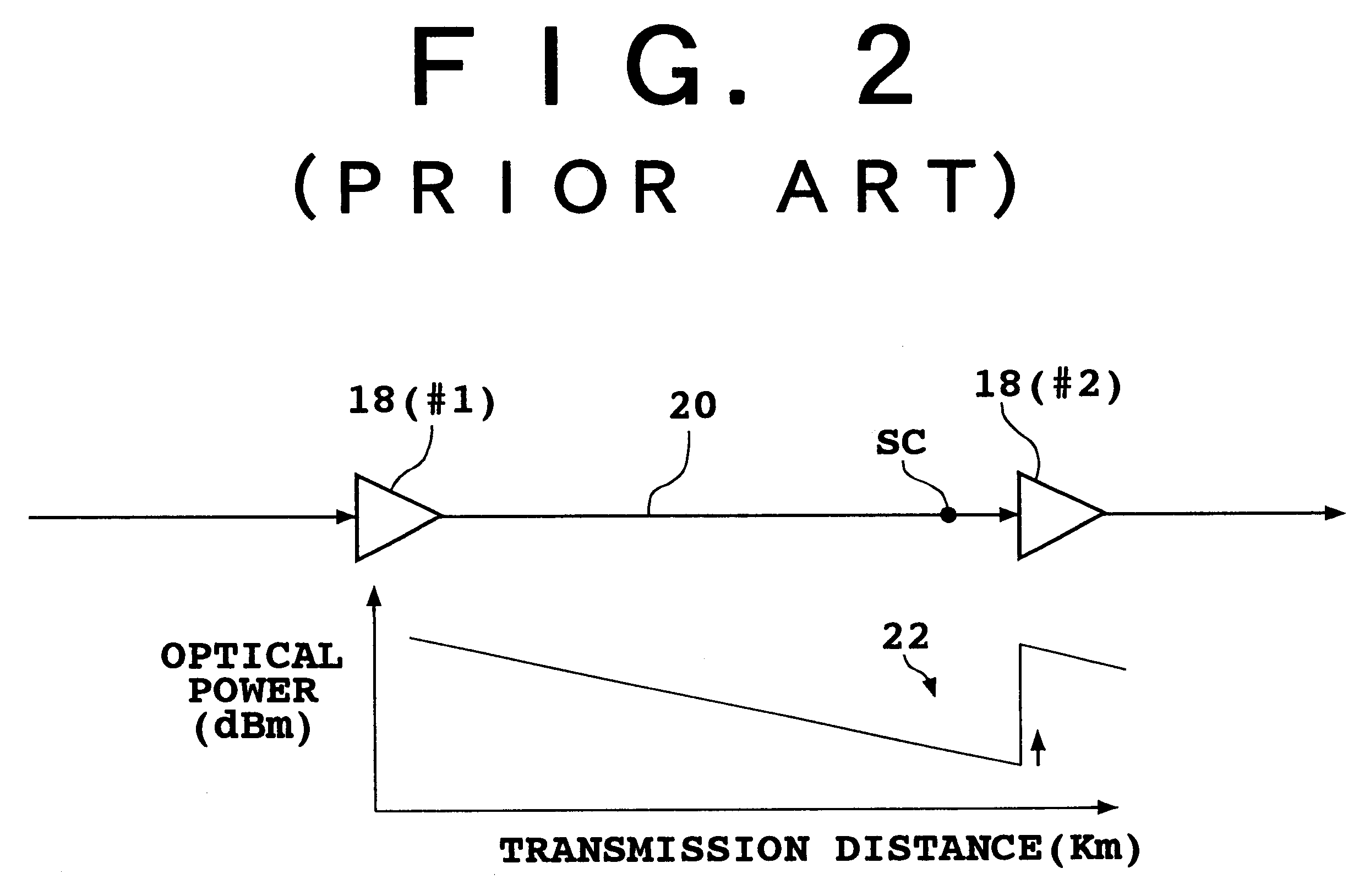
Referring to FIG. 1, the configuration of a conventional optical amplifier that is usable as an optical repeater is shown. The optical amplifier shown in FIG. 1 has an input port 2 and an output port 4. An optical coupler 6, an erbium doped fiber (EDF) 8 as an optical amplifying medium, and an optical coupler 10 are connected between the input port 2 and the output port 4. The EDF 8 has a first end 8A and a second end 8B.

A laser diode (LD) 12 as a pumping source is connected to the optical coupler 10, so that pump light output from the laser diode 12 is supplied through the optical coupler 10 into the EDF 8 from its second end 8B. An optical signal to be amplified is supplied from the input port 2 through the optical coupler 6 into the EDF 8 from its first end 8A. ...


PUM


Abstract

An optical amplifier including a pumping source for supplying pump light to an optical fiber transmission line is provided so that at least a part of the optical fiber transmission line produces Raman amplification to an optical signal. An optical filter unit for selectively switching between a first condition where the optical signal and the pump light are passed and a second condition where the optical signal is passed and the pump light is not passed is connected between the optical fiber transmission line and the optical amplifier. The power of the optical signal in the first condition is compared with that in the second condition, and the characteristics of the optical fiber transmission line, such as a splice loss therein, is evaluated according to the result of this comparison. In the second condition, the residual pump light is not supplied to the optical fiber transmission line, so that a measurement error due to Raman amplification can be eliminated to thereby allow accurate evaluation of the characteristics of the optical fiber transmission line.

Description

BACKGROUND OF THE INVENTION1. Field of the InventionThe present invention relates to a method, device, and system for evaluating the characteristics of an optical fiber transmission line, such as a loss at an optical fiber connection point.2. Description of the Related ArtMethods of manufacturing and using a low-loss (e.g., 0.2 dB / km) optical fiber (e.g., silica fiber) have been established, and an optical fiber transmission system using the optical fiber as a transmission line has been put to practical use. Further, to compensate for losses in the optical fiber transmission line, one or more optical amplifiers for amplifying an optical signal are arranged along the optical fiber transmission line.An optical amplifier known in the art includes an optical amplifying medium for propagating an optical signal, and a pumping source for pumping the optical amplifying medium so that the optical amplifying medium provides a gain in the optical signal. For example, an erbium doped fiber ampl...

Claims


Application Information

Patent Timeline
IPC IPC(8): H01S3/30H01S3/00G01M11/02G01M11/00H04B3/46H04B3/48H04B10/07H04B10/077H04B10/079H04B10/29H04B10/293H04B17/00
CPCH01S3/302H01S3/0014
Inventor DEGUCHI, HIROYUKIHARASAWA, SHIN-ICHIROU
Owner FUJITSU LTD
Why Eureka
Try Eureka