Robot control device having operation route simulation function
Inactive Publication Date: 2002-10-08
FANUC LTD
View PDF26 Cites 38 Cited by
Summary
Abstract
Description
Claims
Application Information
AI Technical Summary
This helps you quickly interpret patents by identifying the three key elements:
Problems solved by technology
Method used
Benefits of technology
Benefits of technology
An object of the present invention is to make it possible to simulate a motion path after it is modified and to obtain information useful in finding an error in teaching of a motion path without using an off-line simulation system and without repeating low-speed playback operation of a real machine each time teaching of a motion path is modified. Another object of the present invention is to make it possible, even when a playback operation of a real machine is started or about to be started after teaching of a motion path is modified, to stop the motion of a robot to prevent an accident if it is found that the modified teaching has an error. By doing so, safety and efficiency of teaching operation is improved.
When the path memory means stores a motion path including data indicative of an interpolation point, and the path comparison means compares a played back motion path and a reference motion path using data indicative of interpolation points on both motion paths, a difference between the played back motion path and the reference motion path can be evaluated with high precision.
The present invention may be arranged such that when the robot is made to perform a real motion by playing back an operation program, if the path comparison means outputs result of the evaluation indicating that there is a difference exceeding the reference value between a played back motion path and a reference motion path, the real motion state of the robot is nullified to prohibit the succeeding motion of the robot. In this arrangement, the robot can be made to perform a real motion checking a difference between a played back motion path and a reference motion path, and when the real motion path deviates largely from the reference path, the real motion of the robot can be stopped to prevent dangers. This is also helpful in finding where mis-teaching occurs.
Problems solved by technology
However, both of the techniques have problems.
Therefore, work efficiency is very low, and an operator bears a large burden.
Therefore, if confirmation of the motion by the low-speed operation is performed each time, large time is consumed in entire teaching operation.
In such cases, large time is additionally consumed in confirmation of a motion resulting from the modified program.
However, in order to raise reliability of the confirmation of a motion, precise reproduction of a robot motion in the off-line system is required, and data input work and the like for such precise reproduction is very burdensome.
Method used
Image
Click on the blue label to locate the original text in one second.
Reading with bidirectional positioning of images and text.
Examples
second embodiment
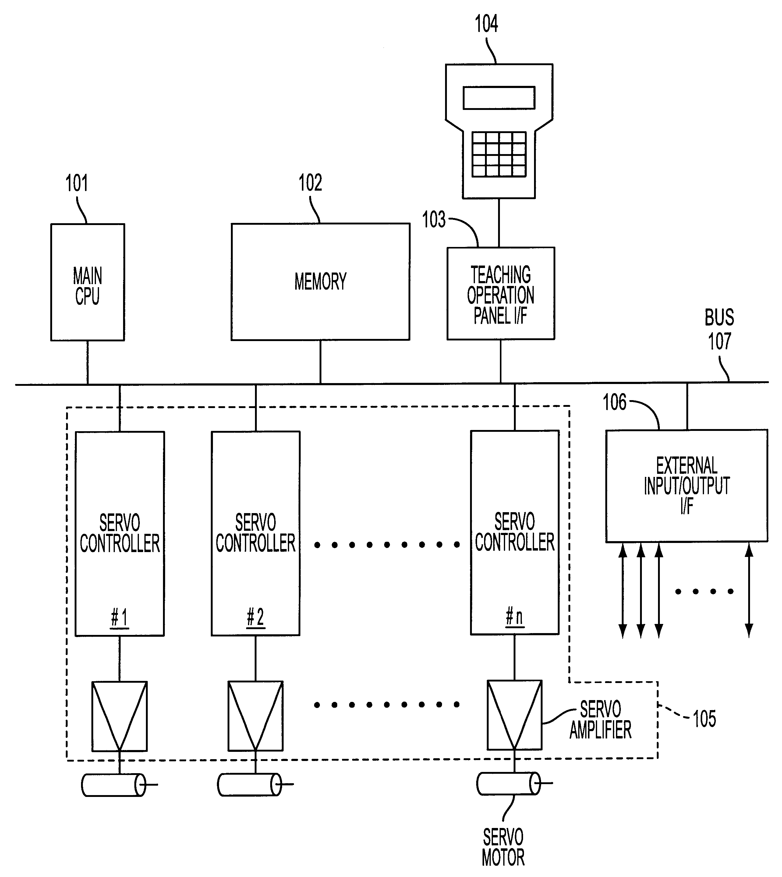
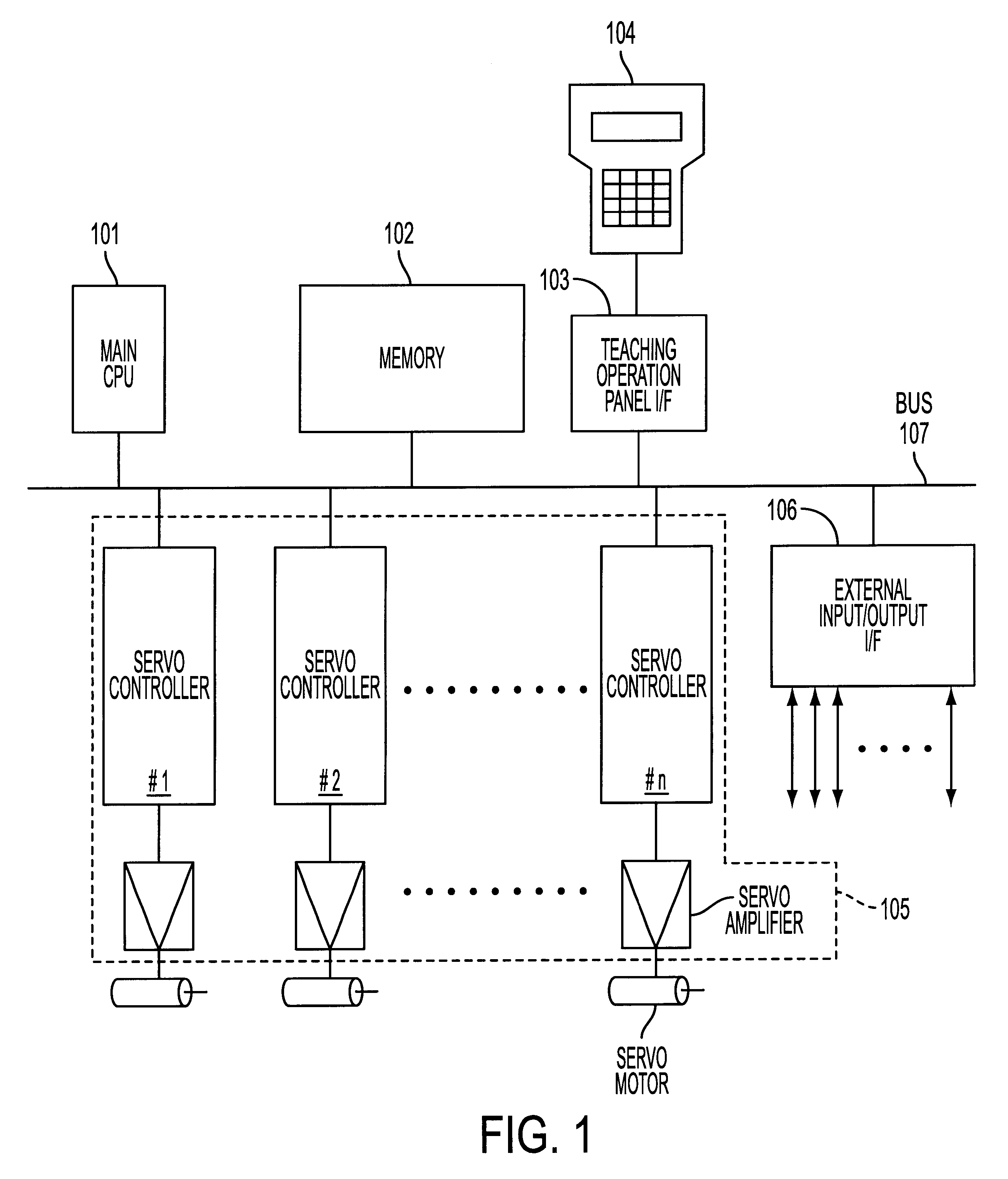
In the processing to be executed according to the first or second embodiment, the following mode flags F1 to F3 are prepared in the memory 102 as means for designating operation or non-operation of a path memory means, a path comparison means, and a robot real machine, respectively. Each of the flags F1 to F3 is a binary register served as a mode selection switch, and takes a value of "0" or "1". An operator can select a desired operation mode by designating the value of each flag to be "0" or "1" in advance through the teaching operation panel 104.
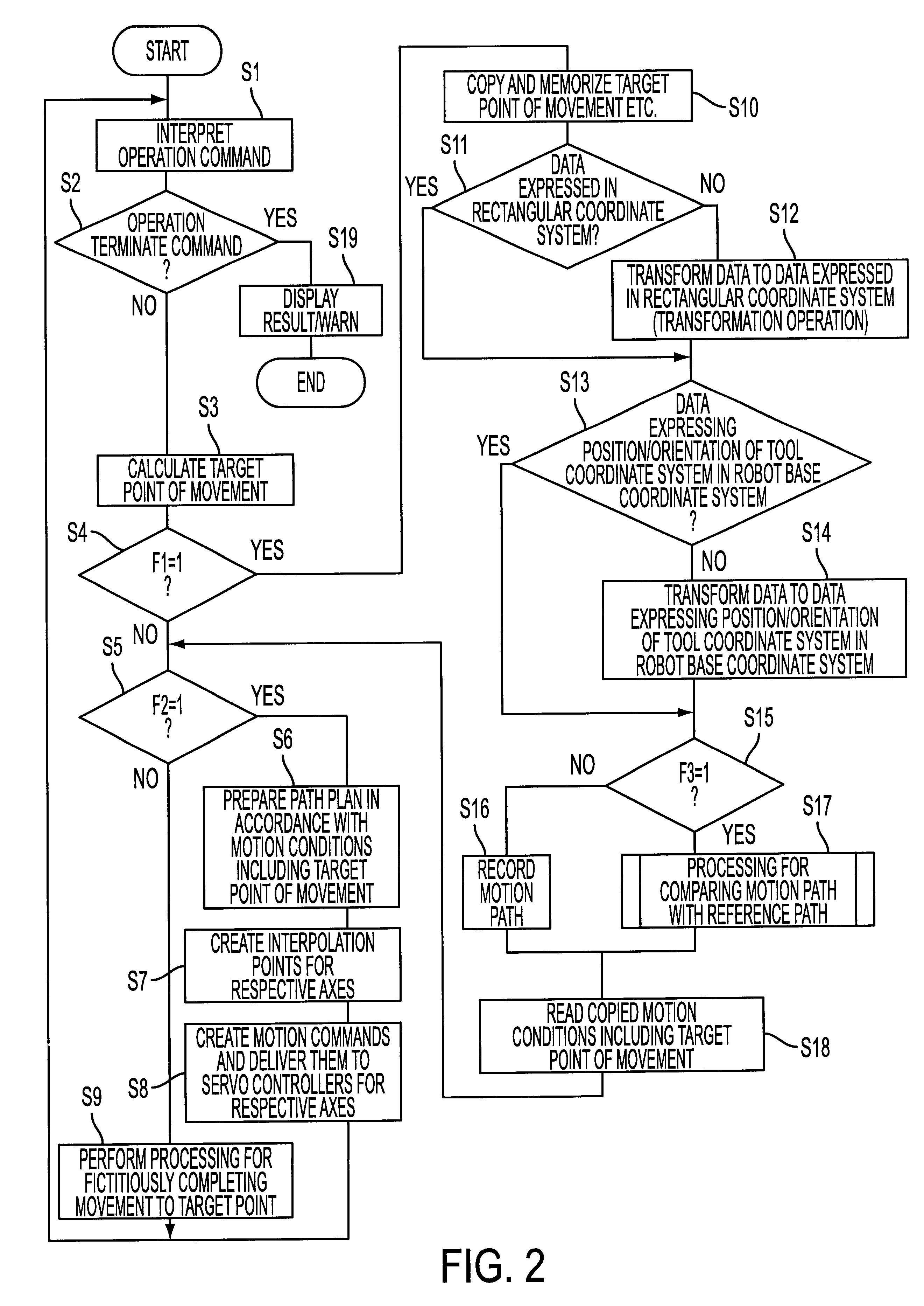
F1: a flag functioning as a switch for selecting ON (F1=1) / OFF (F1=0) of a simulation function which characterizing the present invention.
F2: a flag functioning as a switch for selecting ON (F2=1) / OFF (F2=0) of a real motion (motion of the real robot).
F3: a flag functioning as a switch for selecting On (F3=1) / OFF (F3=0) of a comparison mode (mode for comparing a present path and a reference path)
first embodiment
FIG. 2 is a flowchart for explaining essentials of processing to be executed in the invention. The processing starts which an operator inputs a processing start command through the teaching operation panel 104 after the values of the above flags F1 to F3 are set (mode selections are completed). The CPU 101 reads one block of motion commands (in this embodiment, including an operation terminate command) of an operation program prepared by preceding teaching operation, and interprets (decodes) the command (Step S1).
Generally, operation commands (except for an operation terminate command) includes an absolute-position motion command, a relative-position motion command, a velocity command, a positioning manner at a target position (positioning rate), an external input / output command, and so forth. Unless the read block is an operation terminate command (when the determination in Step S2 is "No"), the procedure proceeds to Step S3, where a target point of movement (position and orientati...
third embodiment
In the processing performed in addition to the above described mode flags F1 to F3, a flag F4 is provided in the memory 102 as means for changing an operation mode of the robot controller. The flag F4 is a digital register used for nullifying a real motion when necessary, and takes a value of "0" or "1" according to the following definition:
F4:F4=1 means that the function of nullifying a real motion is in an on-state (a real motion is blocked). F4=0 means that the function of nullifying a real motion is in an off-state (a real motion is not blocked).
The essentials of processing performed according to the third embodiment is as shown by a flowchart of FIG. 6.
As in the case of the first or second embodiment, the processing starts when an operator inputs a processing start command through the teaching operation panel 104 after the values of the flags F1 to F3 are set (mode selection). The CPU 101 clears the flag F4 to "0" (Step G1) and reads one block of operation commands (including ...
PUM
Abstract
A robot controller capable of finding a mistaught path and avoiding dangers involved in a real motion of a robot without using an off-line simulationsystem. An operation program for confirming safety is played back with the robotcontrol system arranged such that a simulation function is on, a real motion is off, and comparison processing is on. When a played-back path designated by each block is compared with a reference path using data on interpolation points, an interpolation point ordinal index i is incremented by "1" (K1), an interpolation point on a reference path Tref(i) is read (K2) and compared with a corresponding interpolation point on the played-back path T(i). An index of distance d(i) and a distance evaluation index DELTAd(i) are calculated (K3, K4), and tool-tip orientation difference indices f(i) to h(i) and orientation-evaluation indices DELTAf(i) to DELTAh(i) are calculated (K5, K6). Based thereon, it is determined whether or not there is a path difference exceeding a reference value. The processing may be started with a real motion in an on-state, and the real motion of the robot may be nullified when a large path difference is found.
Description
The present invention relates to a motion path simulating technique for preventing an obstruction due to mis-teaching to a robot, which is likely to occur in constructing an automated system using an industrial robot, and securing a safe working environment.In teaching a required motion to a robot, it is very important to confirm that the teaching has been correctly completed, especially that the teaching does not involve an unintended path movement in view of ensuring normal robot operation and also preventing physical injury and interference with a peripheral device. As a method for confirming the teaching in view of the above, the following two methods are conventionally known.(I) A playback operation of the taught program is performed on the condition that the robot moves at a very low speed, for example, by designating a low override value, and safety of a motion is visually confirmed.(II) Using a system for performing teaching and confirmation of a motion in an off-line state,...
Claims
Application Information
Patent Timeline
Application Date:The date an application was filed.
Publication Date:The date a patent or application was officially published.
First Publication Date:The earliest publication date of a patent with the same application number.
Issue Date:Publication date of the patent grant document.
PCT Entry Date:The Entry date of PCT National Phase.
Estimated Expiry Date:The statutory expiry date of a patent right according to the Patent Law, and it is the longest term of protection that the patent right can achieve without the termination of the patent right due to other reasons(Term extension factor has been taken into account ).
Invalid Date:Actual expiry date is based on effective date or publication date of legal transaction data of invalid patent.

