Check patentability & draft patents in minutes with Patsnap Eureka AI!

Method for electronic damping of piezoelectric positioners

a positioner and electronic technology, applied in piezoelectric/electrostrictive device details, piezoelectric/electrostrictive/magnetostrictive devices, piezoelectric/electrostriction/magnetostriction machines, etc., can solve problems such as unsatisfactory resonances or overshoots in position, poor damped oscillations, and substantial mass addition to the positioner

Inactive Publication Date: 2002-10-15
NORTH JR HOWARD L
View PDF6 Cites 13 Cited by
  • Summary
  • Abstract
  • Description
  • Claims
  • Application Information

AI Technical Summary

Problems solved by technology

Such positioners often have very little mechanical damping resulting in undesireable resonances or overshoots in position followed by poorly damped oscillations.
Such added mechanical damping often adds substantial mass to the positioner which reduces its speed of response and its resonant frequency as well as adding significant cost, size, and complexity to the positioner system.
This method works very well but cannot be used in some positioner applications due to constraints on cost, size, and mass added to the positioner.
However, this approach suffers from the following limitations:
The system has no improvement in resistance to oscillations induced by external vibrations or by factors other than the input signal.
The system has no improvement in response when the driving signal must be sinusoidal as in the case of an acoustical loudspeaker.
This method suffers from the limitations of the previous case.
This approach also provides no improvement in resistance to mechanical oscillations induced by external vibrations or to factors other than the input command signal.
Even when a step change in driving voltage is applied to a positioner through a series resistor there are often poorly damped oscillations of positioner motion.
There is a large overshoot of capacitor finel voltage and poorly damped oscillations when the damping is 0.2 of critical damping.

Method used


Image

  • Method for electronic damping of piezoelectric positioners
  • Method for electronic damping of piezoelectric positioners
  • Method for electronic damping of piezoelectric positioners

Examples


main embodiment

OPERATION--MAIN EMBODIMENT

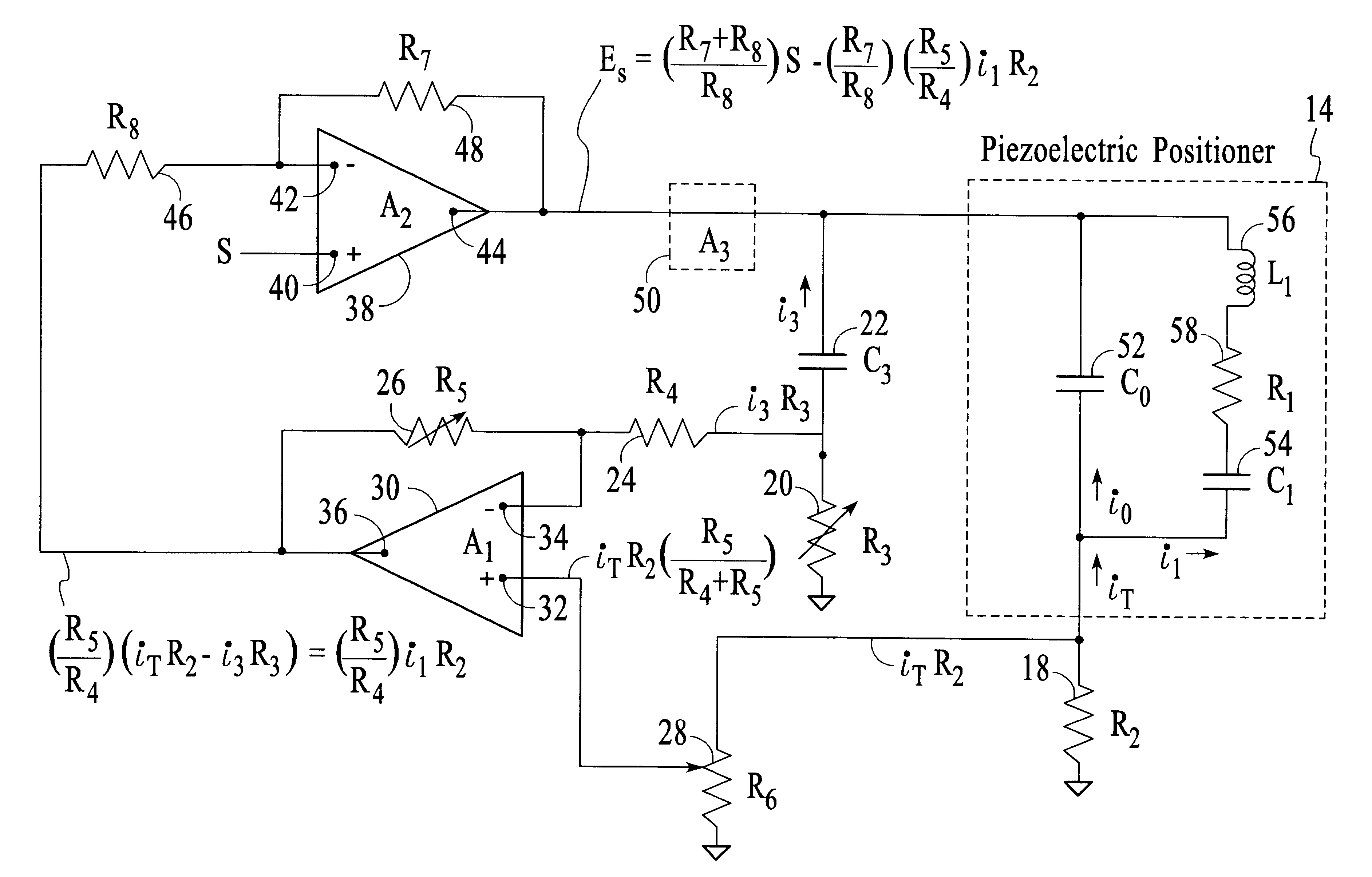
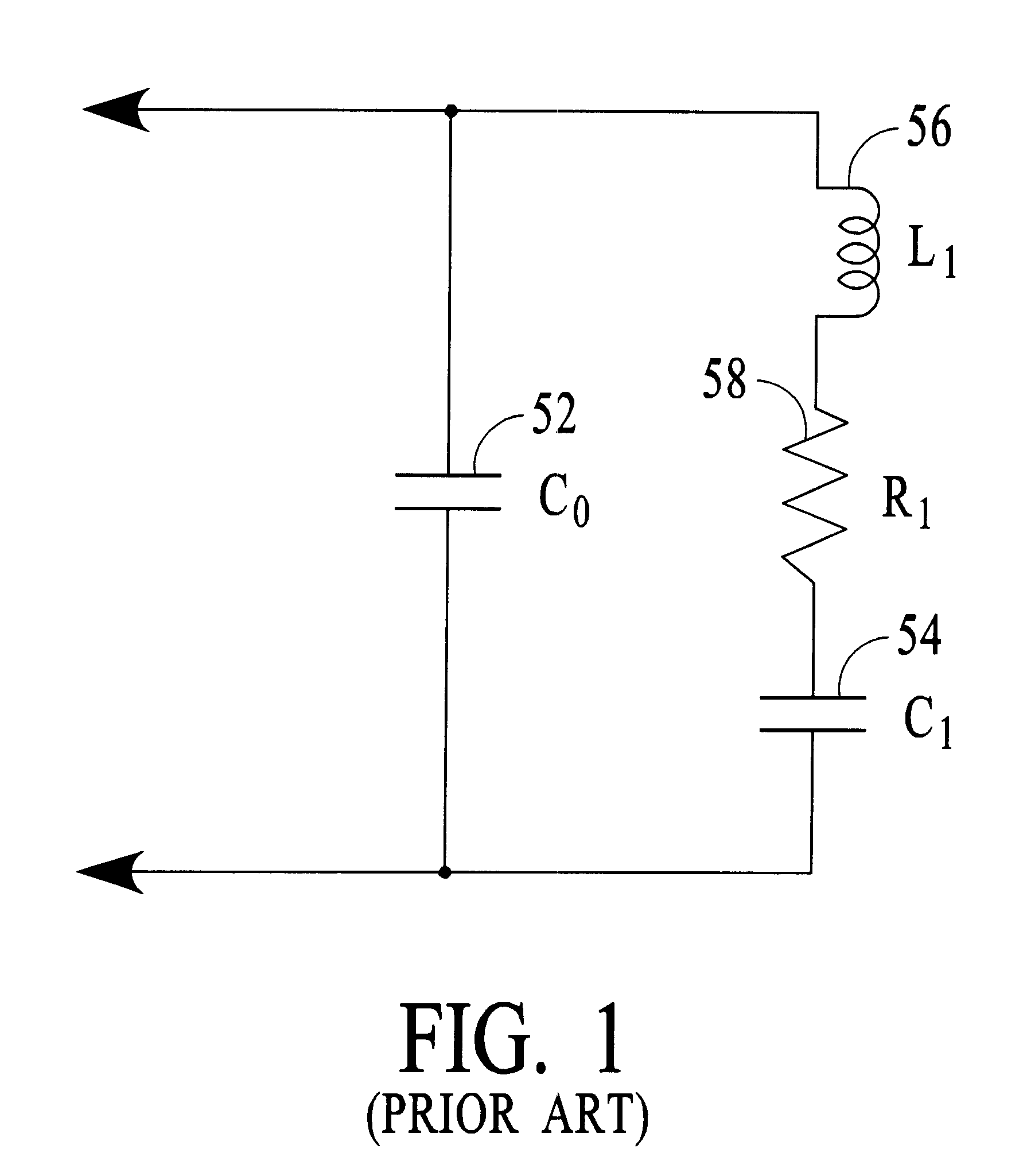
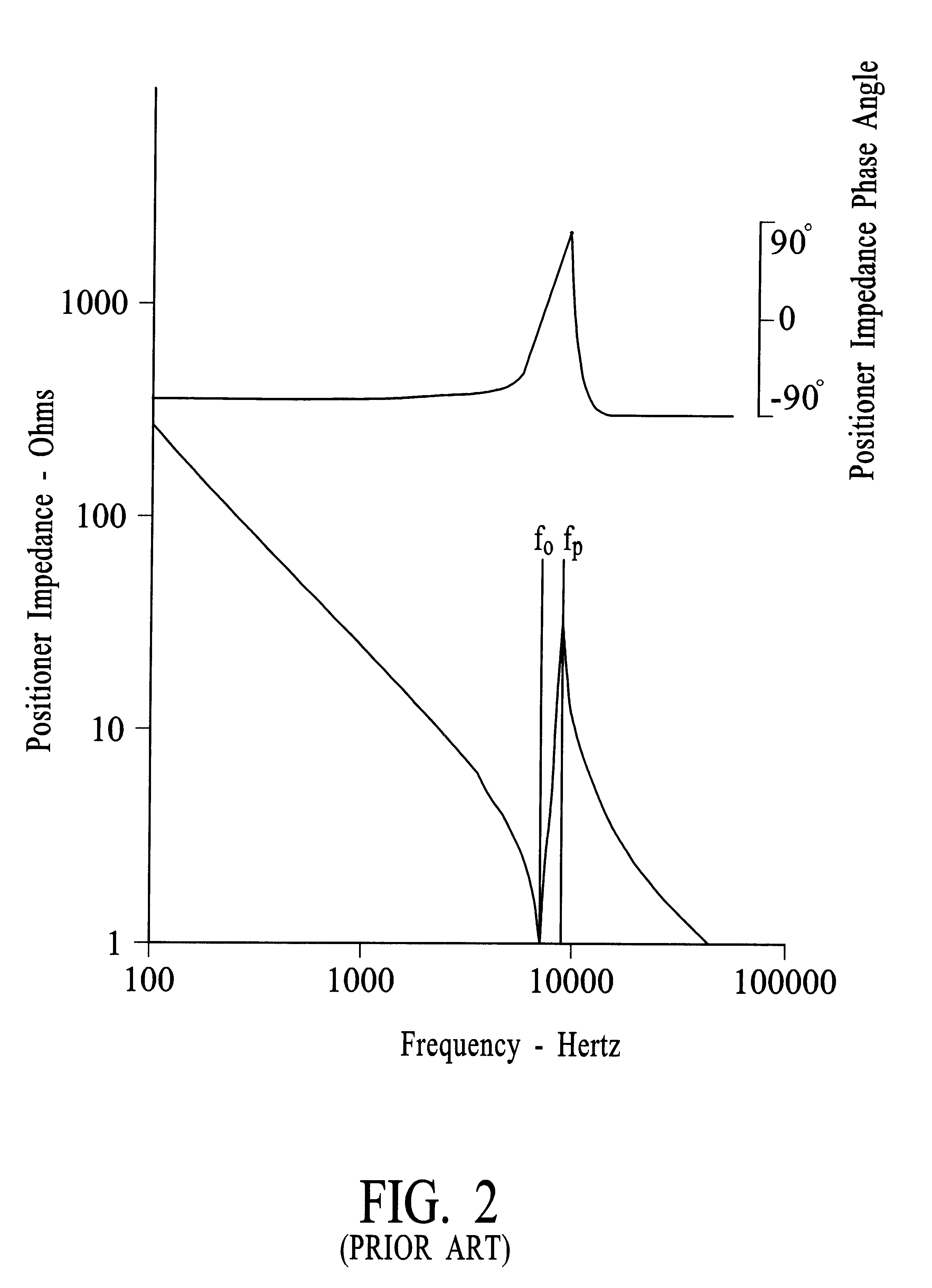
A piezoelectric positioner mechanically is a spring mass system with some damping. This system can be represented electrically by the substitute circuit diagram shown on FIG. 1. The electrical impedance magnitude and phase angle of a piezoelectric positioner and its load mass is shown on FIG. 2 versus frequency and is expressed by Eq.1: ##EQU1##

With small values of R.sub.1 this impedance goes toward a zero at ##EQU2##

and goes toward a pole at ##EQU3##

where C.sub.T is the series capacitance of C.sub.0 and C.sub.1 and ##EQU4##

At .omega..sub.0 =2.pi.f.sub.0 the impedance of the series L.sub.1 R.sub.1 C.sub.1 decreases to R.sub.1 and the current through L.sub.1 R.sub.1 C.sub.1 greatly increases for a fixed applied sinusoidal voltage compared to the current at lower and higher frequencies. This higher current causes large displacements of the load coupled to the piezoelectric positioner and a resonance occurs.

At frequencies higher than f.sub.0 the impedance of t...


PUM


Abstract

Electronic damping may be provided to a piezoelectric positioner by developing a voltage signal proportional to the current through the dynamic impedance portion of the positioner impedance and then reducing the voltage applied to the positioner in proportion to this voltage signal. This dynamic impedance portion of the positioner impedance consists of an inductance, a resistance, and a capacitance in series. The inductance is the electrical equivalent of the positioner distributed mass and its load mass. The capacitor is the electrical equivalent of the compliance of the positioner and its support structure. The resistor is the electrical equivalent of the damping of the positioner and its load. The voltage signal proportional to the current through this dynamic impedance is obtained by subtracting from a first voltage proportional to the total current through the positioner a second voltage proportional to the current through the static capacitance portion of the positioner impedance. This first voltage is obtained from a resistor in series with the positioner. This second voltage is not obtainable directly but is equal to a third voltage synthesized by a model impedance comprising a capacitor and resistor in series having the same RC time constant as that of the positioner static capacitance and the resistor in series with the positioner where both resistor / capacitor combinations are energized by the same voltage driving the positioner.

Description

1. Field of InventionThis invention relates to electronic means to provide a velocity signal for a piezoelectric positioner and the use of this velocity signal to provide damping of the mechanical vibrations thereof.2. Description of Prior ArtMany positioning systems have a position response related to an applied control signal voltage. Piezoelectric materials have the capacity to convert electric potentials into mechanical strains and vice versa. Thus a piezoelectric positioner has an output position that is substantially linearly proportional to an applied control voltage. Examples of piezoelectric positioner use are the positioning of a micromirror in an optical switch by Riza et al in U.S. Pat. No. 5,208,880, the positioning of a catcher tube in a catcher tube particle sorter by North in U.S. Pat. No. 5,030,002, and the psitioning of a surface in an acoustical loudspeaker. Such positioners often have very little mechanical damping resulting in undesireable resonances or overshoo...

Claims


Application Information

Patent Timeline
IPC IPC(8): H01L41/00H01L41/04H02N2/06
CPCH01L41/042H02N2/062H10N30/802
Inventor NORTH, JR., HOWARD L.
Owner NORTH JR HOWARD L
Features
  • R&D
  • Intellectual Property
  • Life Sciences
  • Materials
  • Tech Scout
  • Unparalleled Data Quality
  • Higher Quality Content
  • 60% Fewer Hallucinations
Learn More