Method for packing catalyst and device therefor

a catalyst and catalyst technology, applied in the directions of transportation and packaging, packaging goods type, liquid handling, etc., can solve the problems of insufficient method for filling catalysts uniformly, too much time and labor, and too many socks

Inactive Publication Date: 2002-10-22
TOYO ENG CORP
View PDF3 Cites 72 Cited by
  • Summary
  • Abstract
  • Description
  • Claims
  • Application Information

AI Technical Summary

Problems solved by technology

Accordingly, the sock method takes too much time to be said suitable.
However, the method is not adequate for filling a catalyst uniformly in the space formed by the inner wall of the reactor and the outer walls of the tubes.
To fill a catalyst in

Method used


Image

  • Method for packing catalyst and device therefor
  • Method for packing catalyst and device therefor
  • Method for packing catalyst and device therefor

Examples


example 1

Preliminary Test 1

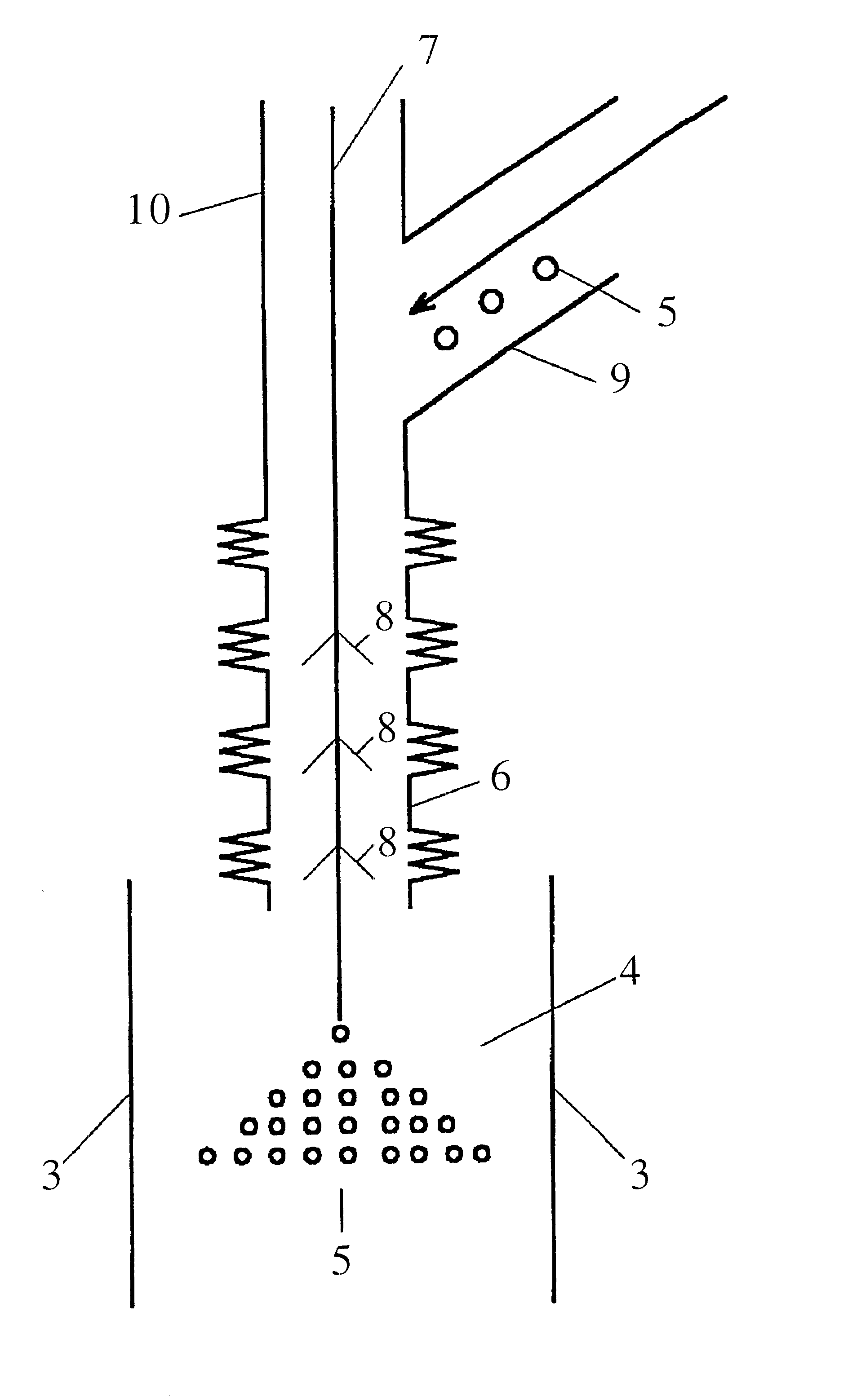
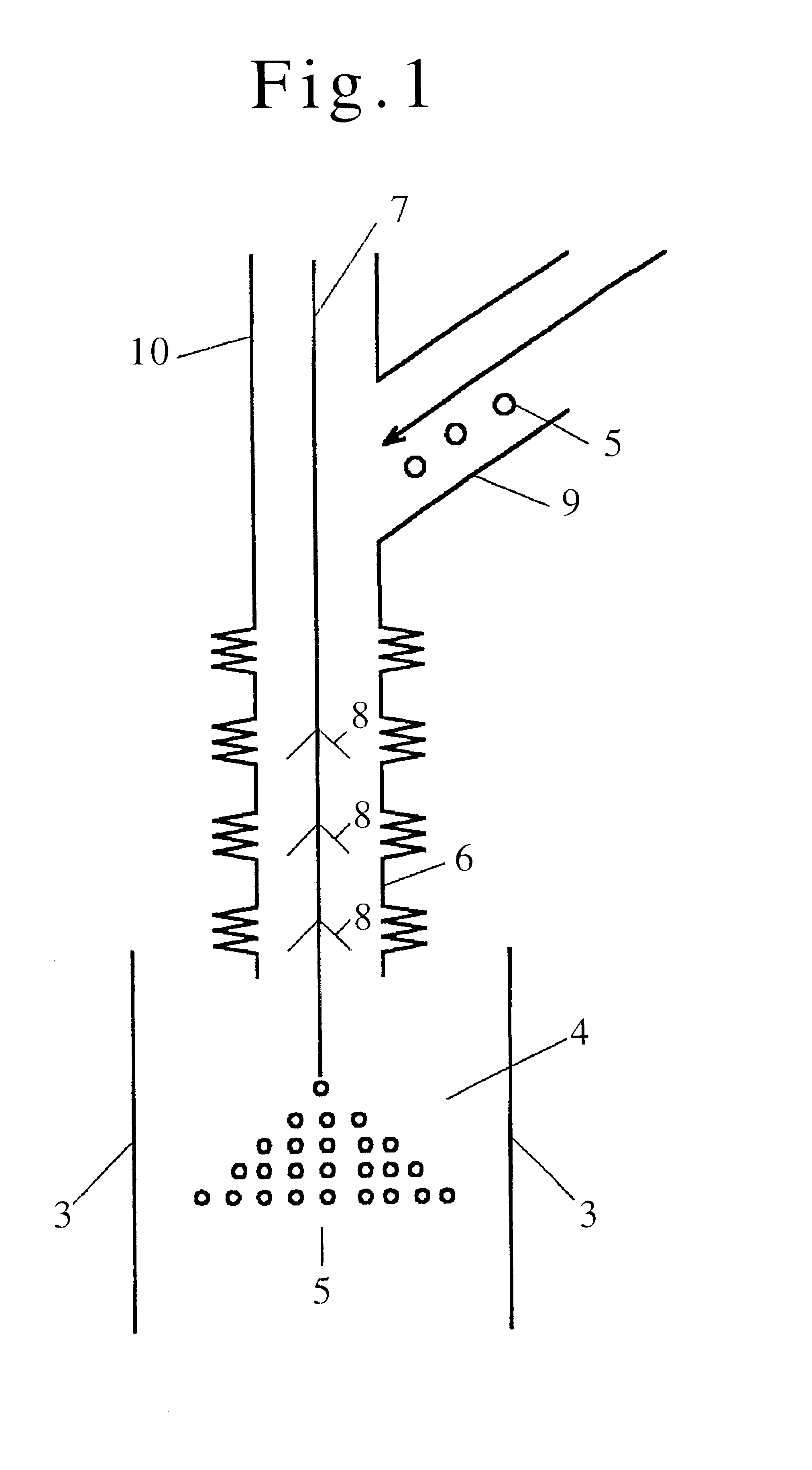
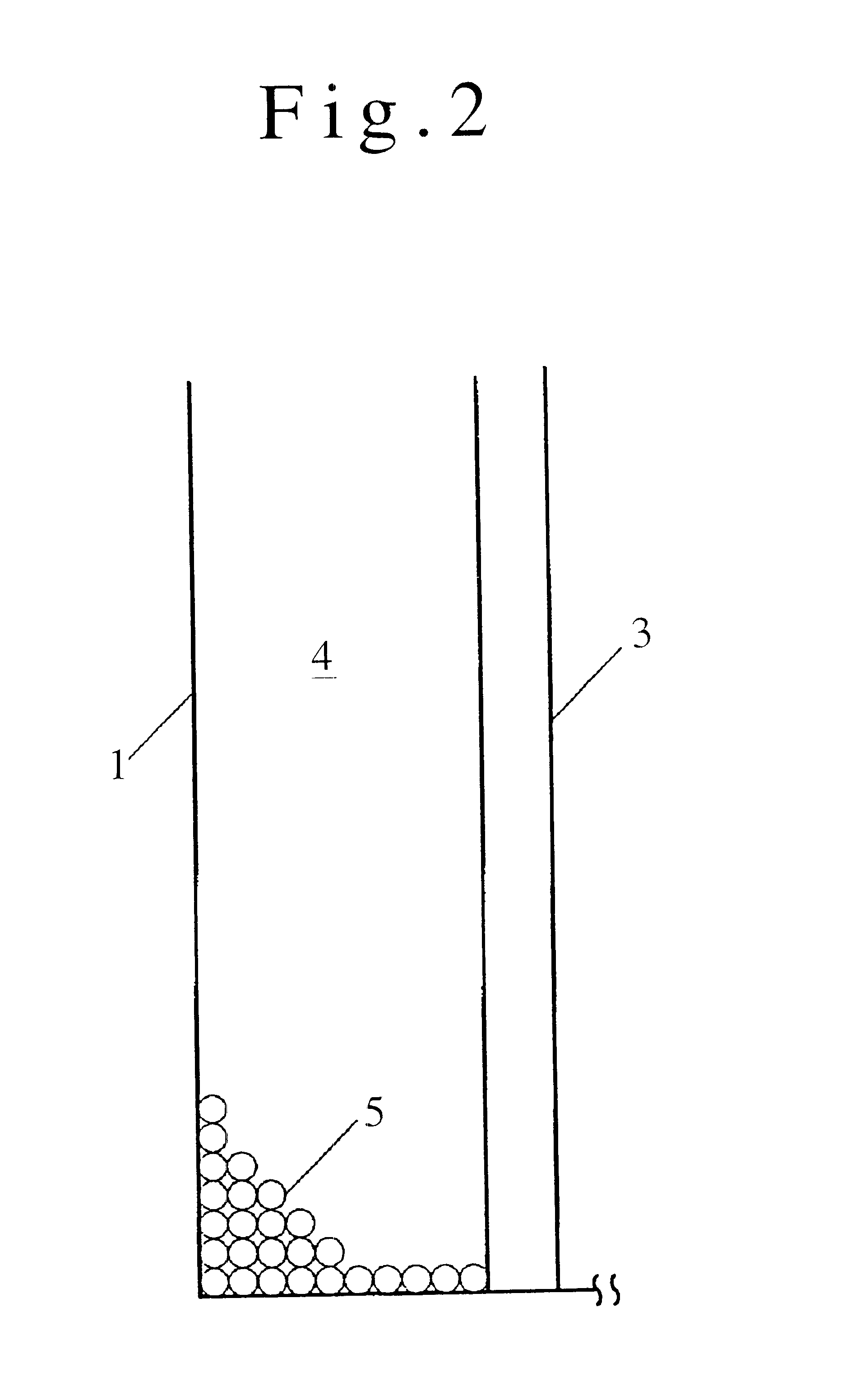
In packing a catalyst in a reactor 1, the following preliminary test was carried out. The catalyst 5 had a cylindrical shape, a diameter of 5 mm, a length of 5 mm, an angle of repose of 30 degrees, and an apparent specific gravity of 1,000 kg / m.sup.3.

Brushes 8 of type 1 were used at installing intervals of 0.5 m. Their material was polyethylene. A flexible tube of 1 m with an inner diameter of 100 mm was used, into which brushes of the type 1 were inserted. The catalyst 5 was fed in the flexible tube and eventually allowed to fall down onto an iron plate. Then, it was observed whether or not the catalyst was broken.

As a result, it was found that the catalyst 5 was not broken up to a falling height of 4 m even when caused to fall down onto an iron plate.

example 2

Preliminary Test 2

In Example 1, the catalyst was allowed to fall down onto an iron plate. In this example, however, it fell down onto a 30-mm layer of the catalyst piled on an iron plate. The test was carried out under the same conditions as those used in Preliminary Test 1. It was found that the catalyst was not broken up to a falling height of 4 m.

example 3

Preliminary Test 3

Using the catalyst 5 and brushes 8 of Example 1, the test was carried out by using a flexible tube with an inner diameter of 100 mm and setting the intervals of the brushes 8 at 1 m maximum, in order to confirm that no breakage of the catalyst 5 took place upon collision with the flexible tube 6 and the brushes 8. As a result, no breakage of the catalyst was found upon collision with the flexible tube 6 and the brushes 8.

From these results, it was confirmed that brushes 8 having any elastic shapes capable of absorbing the falling speed of the catalyst were satisfactorily used.


PUM

PropertyMeasurementUnit
Angleaaaaaaaaaa
Flexibilityaaaaaaaaaa
Areaaaaaaaaaaa

Abstract

In a reactor in which reaction tube(s), cooling tubes, heating tubes or combinations thereof are provided, a method for packing a catalyst comprising a step of packing the catalyst in the space formed between the inner wall of the reactor and the outer walls of the tubes by passing the catalyst through a flexible tube provided in the inside of the reactor and having a means to absorb the impact to the catalyst and thereby feeding the catalyst along the inner wall of the reactor with the falling distance of the catalyst maintained within a certain range and a step of fluidizing the catalyst thus-packed in said space, and a device for effecting the method.

Description

The invention relates to a method for packing a catalyst and a device therefor. More specifically, the invention relates to a method for packing a catalyst quickly and uniformly in the space formed between the inner wall of a reactor in which a plural number of reaction tube(s), cooling tubes, heating tubes or combinations thereof are provided, and the outer walls of the tubes, and a device therefor.DESCRIPTION OF THE RELATED ARTAs illustrated in ammonia synthesis reactors, methanol synthesis reactors and the like, there are a variety of synthesis processes in each of which a catalyst is filled in a plural number of reaction tubes arranged in the reactor to obtain a desired product. In these processes, various methods are devised to fill the catalyst in the inside of the reaction tubes. An example teaches that a given amount of a catalyst is put in, what is called, a sock having a function capable of opening at the tip, the sock being then inserted into each reaction tube, and the t...

Claims


Application Information

Patent Timeline
IPC IPC(8): B01J8/02B01J8/00B01J8/06B01J4/00B65B1/04
CPCB01J8/002B01J8/003B01J8/06B01J2208/00752B01J2208/00778
Inventor YANARU, HIDEAKINAKAMURA, HITOSHIYANAGISAWA, YUZURU
Owner TOYO ENG CORP
Why Eureka
Try Eureka