Reformer

a technology of reformer and catalyst, applied in the field of reformer, can solve the problems of complex structure of reformer, difficulty in loading and unloading catalyst, and catalysts that are sometimes broken during operation, so as to reduce the methane conversion efficiency and heat transfer efficiency, and reduce the occurrence of problems

Inactive Publication Date: 2005-12-29
TOYO ENG CORP
View PDF9 Cites 44 Cited by
  • Summary
  • Abstract
  • Description
  • Claims
  • Application Information

AI Technical Summary

Benefits of technology

[0009] An object of the present invention is to provide a reformer which can restrain the occurrence of problems caused by thermal expansion and thermal stress without decreasing the methane conversion efficiency and heat transfer efficiency while having a structure suitable for a larger size reformer. Another object of the present invention is to provide a reformer capable of using a wide range of gases as the high-temperature heat source necessary for the reforming reaction.
[0014] Since the fixed tube plate located close to the supply port for the heating gas is cooled by the cooling means, the fixed tube plate is kept at a relatively low temperature. On the other hand, the floating head is provided at a position close to the discharge port for the heating gas, the temperature of the heating gas is lower, so that the floating head is not exposed to high temperatures, resulting on a reformer that is mechanically stable.
[0015] Also, one end of the reaction tube holding the catalyst is connected to the floating head via the first flexible tube joint, thereby absorbing a difference in thermal expansion between the reaction tubes. Further, the floating head is connected to the raw material gas inlet of the vessel via the second flexible tube joint, by which a large difference in thermal expansion of the whole reformer is absorbed. Therefore, tube buckling, tensile fracture, and the like caused by the difference in thermal expansion can be avoided. Moreover, since both of the first flexible tube joint for connecting the reaction tube to the floating head and the second flexible tube joint for connecting the floating head to the raw material gas inlet are disposed in areas having a relatively low temperature in the reformer, these joints remain reliable in the long-term operation. Also, since these joints are disposed in portions not requiring a heat insulating material, the maintenance of these joints can be performed easily.

Problems solved by technology

However, loading and unloading of the catalyst is difficult because the catalyst must be loaded into or unloaded from an annular portion between the outer and inner tubes while avoiding an obstacle created by a manifold of the inner tubes in an upper region.
Also, the catalyst is sometimes broken during operation because of axial movement caused by a difference in thermal expansion between the outer and inner tubes.
And since a raw material gas introduction section and a reformed gas discharge section are provided on one side of the reformer, the reformer is complicated in structure, making it difficult to increase the size of the reformer.
Therefore, the temperature of the high-temperature gas is hardly utilized effectively, and the heat transfer efficiency decreases.
Also, in principle, the reformers of this type cannot be used with a high-temperature gas that cannot be mixed with the process gas (i.e., the raw material gas and the reformed gas obtained by reforming the raw material gas).
For example, this type of reformers cannot be used when the high-temperature gas is helium heated by fission heat of a nuclear reactor.
Therefore, high thermal stress is likely to occur at the floating head, so that it is difficult to use this reformer in applications in which the high-temperature gas is introduced directly from the outside of the reformer.
Also, the reformer of this type is unsuitable for a large-size reformer because the thermal stress occurring at the floating head is especially remarkable in a large-size reformer.

Method used


Image

  • Reformer
  • Reformer
  • Reformer

Examples


examples

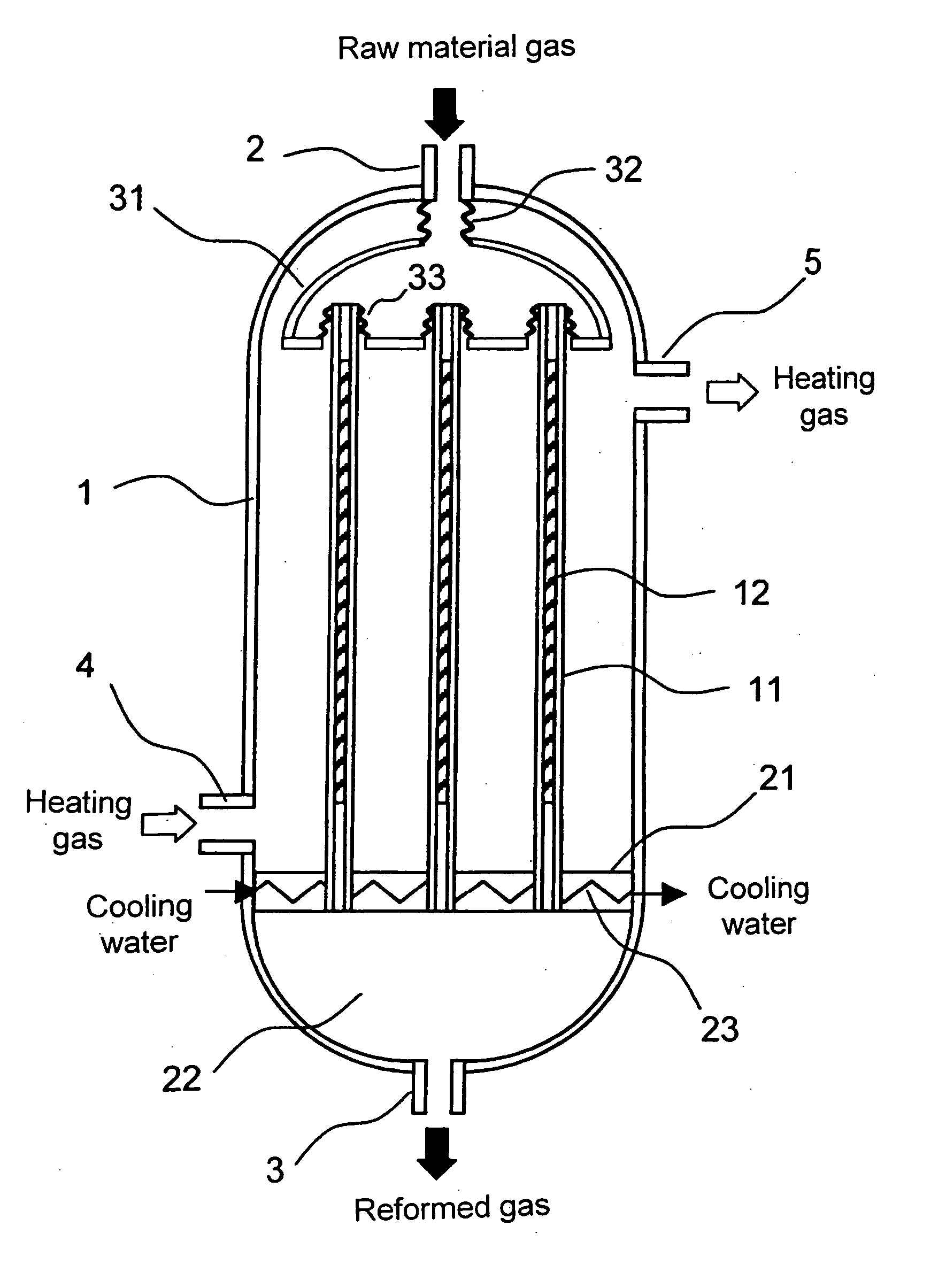
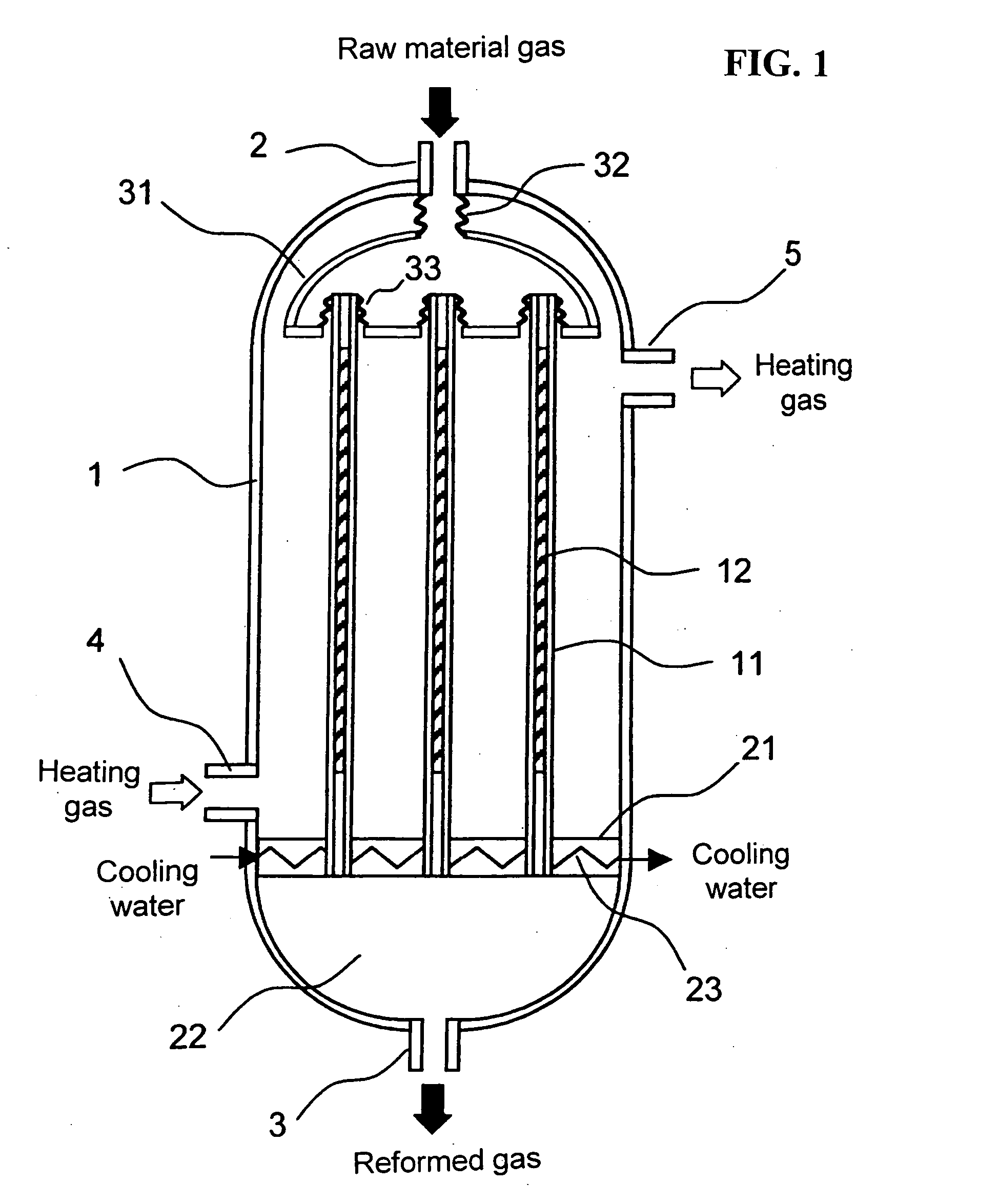
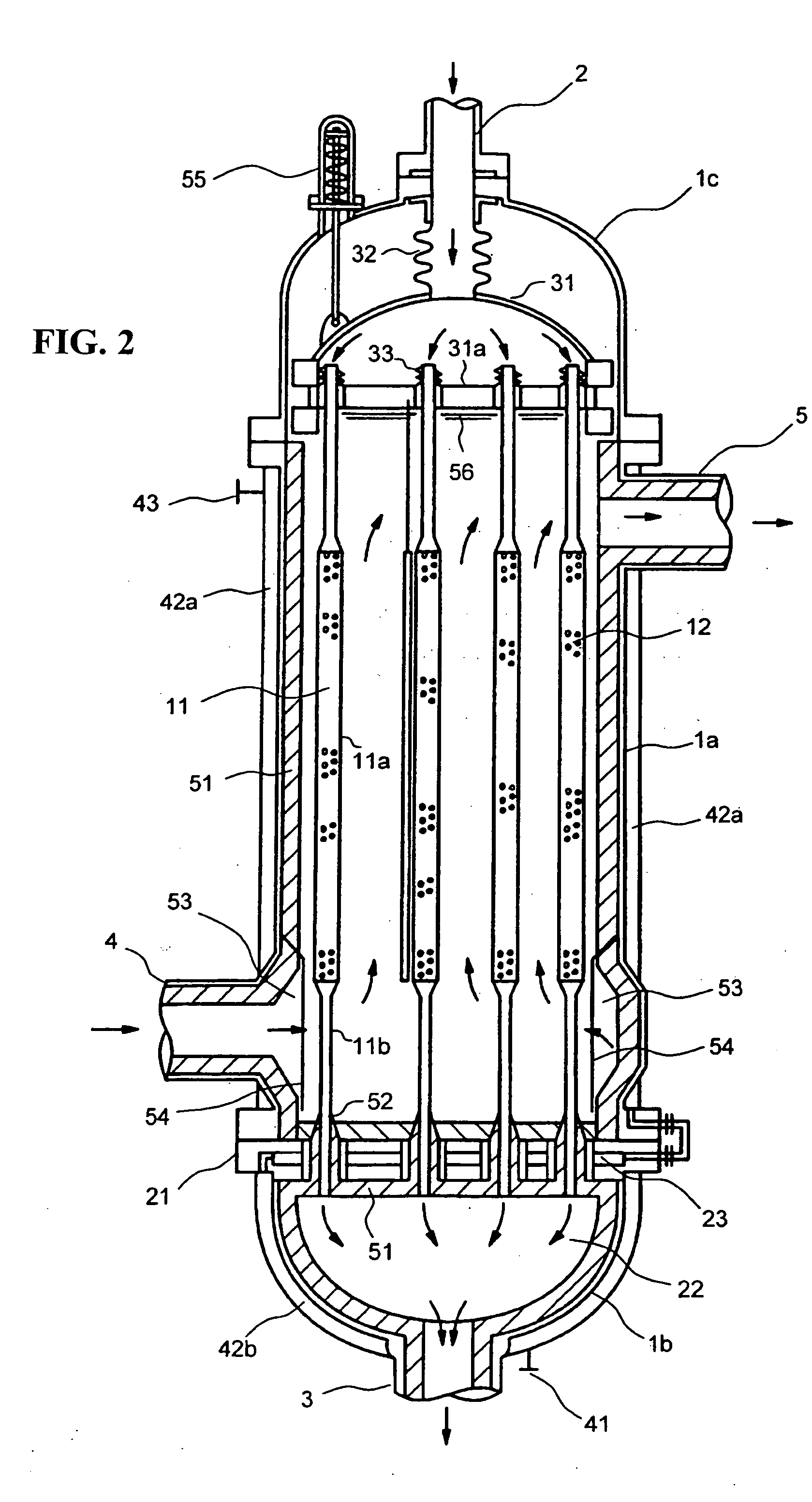
[0046] An example of a reformer in accordance with the present invention is shown in FIG. 2. In this figure and the following description, explanation is given of a vertical reformer having the floating head in an upper part thereof. However, the reformer may be of a vertical type or a horizontal type, and the floating head may be located in an upper part or in a lower part.

[0047] The vessel of the reformer is made up of a shell 1a and shell covers 1b (shell cover on the fixed tube plate side) and 1c (shell cover on the floating head side, namely, a floating head cover) provided below and above the shell, respectively.

[0048] The plurality of reaction tubes 11 each holding the catalyst 12 necessary for the reforming reaction are arranged, and the lower end of each of the tubes is attached to the fixed tube plate 21 which is fixed to the vessel. The upper end of the tube is attached to a floating tube plate 31a of the floating head 31 via a first flexible tube joint 33, such as a be...


PUM

PropertyMeasurementUnit
temperatureaaaaaaaaaa
diameteraaaaaaaaaa

Abstract

A device to reform a raw material gas into a synthesis gas rich in hydrogen and carbon monoxide is disclosed. The device includes a vessel, a floating head, a plurality of reaction tubes, inlets and outlets for raw material and heating gases, and a cooled fixed tube plate.

Description

BACKGROUND OF THE INVENTION [0001] 1. Field of the Invention [0002] The present invention relates to a reformer for producing a synthesis gas from a raw material, such as a natural gas. More particularly, it relates to a heat exchanger type reformer which produces a synthesis gas rich in hydrogen and carbon monoxide by reforming, with steam, a raw material, such as a hydrocarbon gas, by utilizing a high-temperature gas as a heating source. [0003] 2. Background of the Invention [0004] There is known a heat exchanger type reformer that utilizes combustion gas or a high-temperature gas obtained from a secondary reformer as a heating source to cause a hydrocarbon to react with steam (reformed) in the presence of a catalyst to produce a gas that is rich in hydrogen and carbon monoxide. [0005] Conventionally, heat exchanger type reformers, as disclosed in U.S. Pat. No. 4,690,690 and Japanese Patent No. 3442167, comprise a bayonet tube, in which an inner tube is inserted in an outer tube w...

Claims


Application Information

Patent Timeline
Patent Type & Authority Applications(United States)
IPC IPC(8): B01J8/00B01J8/06C01B3/26C01B3/38F28F9/02
CPCB01J8/008B01J8/065B01J8/067B01J2208/00176B01J2208/00203B01J2208/00212F28F9/0241B01J2208/0053C01B3/384C01B2203/0233C01B2203/0805F28F9/0229B01J2208/00221Y02P20/10
Inventor SAKAI, KENJIHIROTANI, KUNIO
Owner TOYO ENG CORP
Why Eureka
Try Eureka