Adjustable shear valve mud pulser and controls therefor

a technology which is applied in the field of mudpulsing valve and control system, can solve the problems of system disadvantage of taking flow away from the bit, slow data transmission rate, and inability to distinguish between adjacent pulses, etc., and achieve the effect of improving data transmission ra

Inactive Publication Date: 2002-10-22
BAKER HUGHES INC
View PDF6 Cites 83 Cited by
  • Summary
  • Abstract
  • Description
  • Claims
  • Application Information

AI Technical Summary

Benefits of technology

A telemetry system involving a shear-type mud pulser valve as the preferred embodiment is described. The control system includes a motor driver for the mud pulser which, in essence, moves one movable plate with respect to a stationary plate to create openings of various sizes. Pressure is sensed uphole of the pulser valve and is compared in real time to the desired pressure pulse amplitude. By allowing different relative rotational positions of the rotatable plate with respect to the stationary plate, different amplitudes can be achieved to further enhance the transmission of data to the surface. The control system compensates for wear in the mud pulser valve itself as well as drastic changes in mud flow and pressure. The configuration is simple and not prone to fouling from grit or other particles in the mud. The system is capable of creating an initial baseline array of a variety of pulse amplitudes, and thereafter providing the required relative rotation between the stationary and rotatable plates so as to be able to duplicate the baseline pulse amplitudes despite changes in the valve condition or in the flowing conditions of the mud.

Problems solved by technology

The rate of transmission of data is relatively slow due to pulse spreading, distortion, attenuation, modulation rate limitations, and other destructive forces such as ambient noise in the drillstring.
However, increasing the pulse frequency makes it more difficult to distinguish between adjacent pulses because of short resolution periods.
These systems have a disadvantage of taking flow away from the bit.
Pulse detection at the surface can sometimes become difficult due to attenuation and distortion of the signal and the presence of noise generated by the mud pumps, the downhole mud motor, and elsewhere in the drilling system.
The presence of grit and other particles in the mud also creates certain operational problems for transducers in the drillstring.
However, this system suffers from various disadvantages.
This is also because erosion on the orifice or poppet affects the amplitude of the pulse generated and the control system described in U.S. Pat. No. 5,586,084 has no provisions for compensation for such erosion effects.
Additionally, the use of bypass passages in drilling mud service also creates potential plugging problems in the small components, which would undermine the effectiveness of that system.
The system of the prior art thus requires the use of many relief valves or a motor-driven variable restrictor which further presents operational difficulties in mud service.
These components must be calibrated for the poppet and orifice combination in its new condition and cannot respond effectively to effects of erosion or dramatic differences in mud flow rates and operating pressures.

Method used


Image

  • Adjustable shear valve mud pulser and controls therefor
  • Adjustable shear valve mud pulser and controls therefor
  • Adjustable shear valve mud pulser and controls therefor

Examples


Embodiment Construction

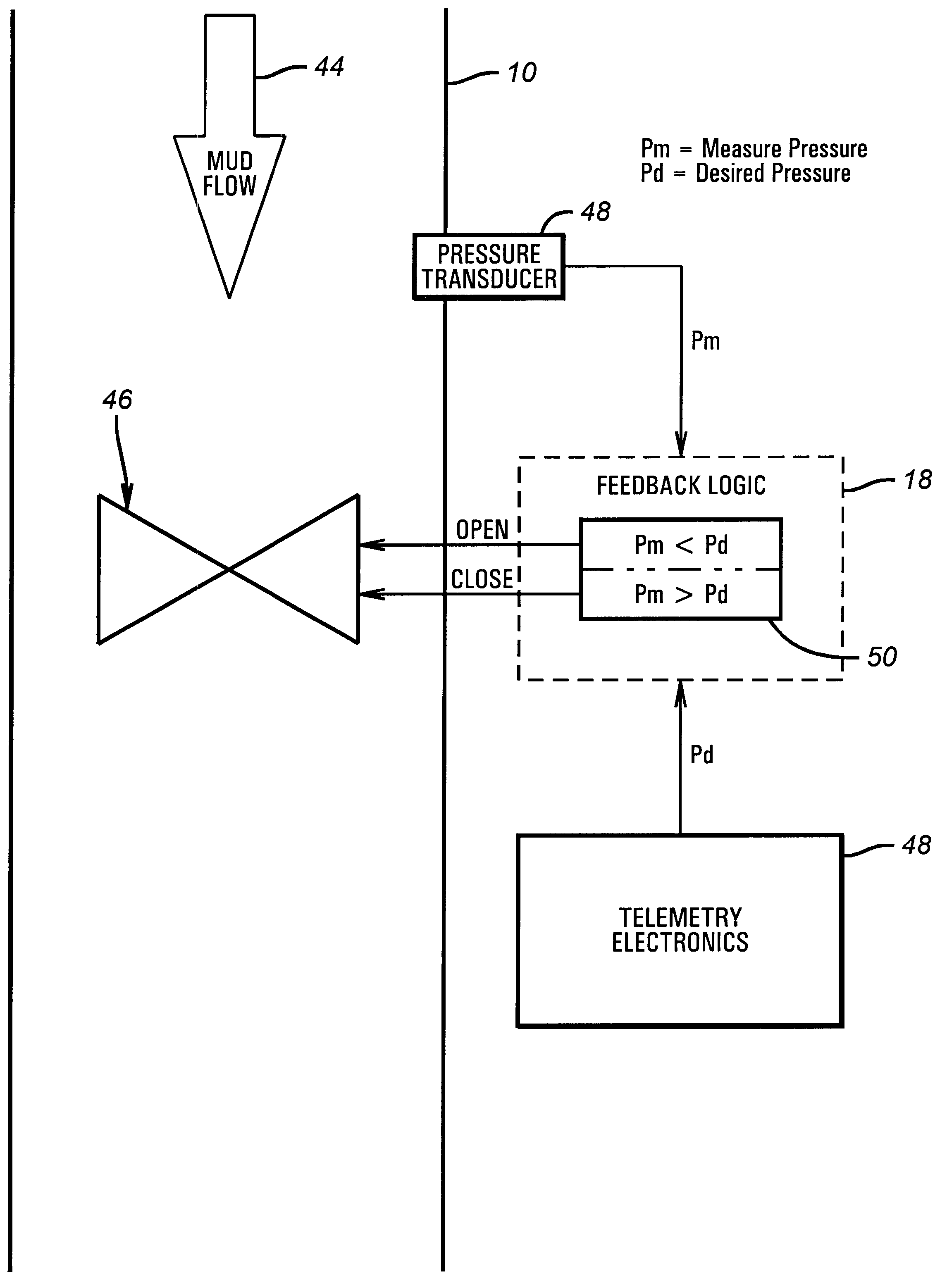
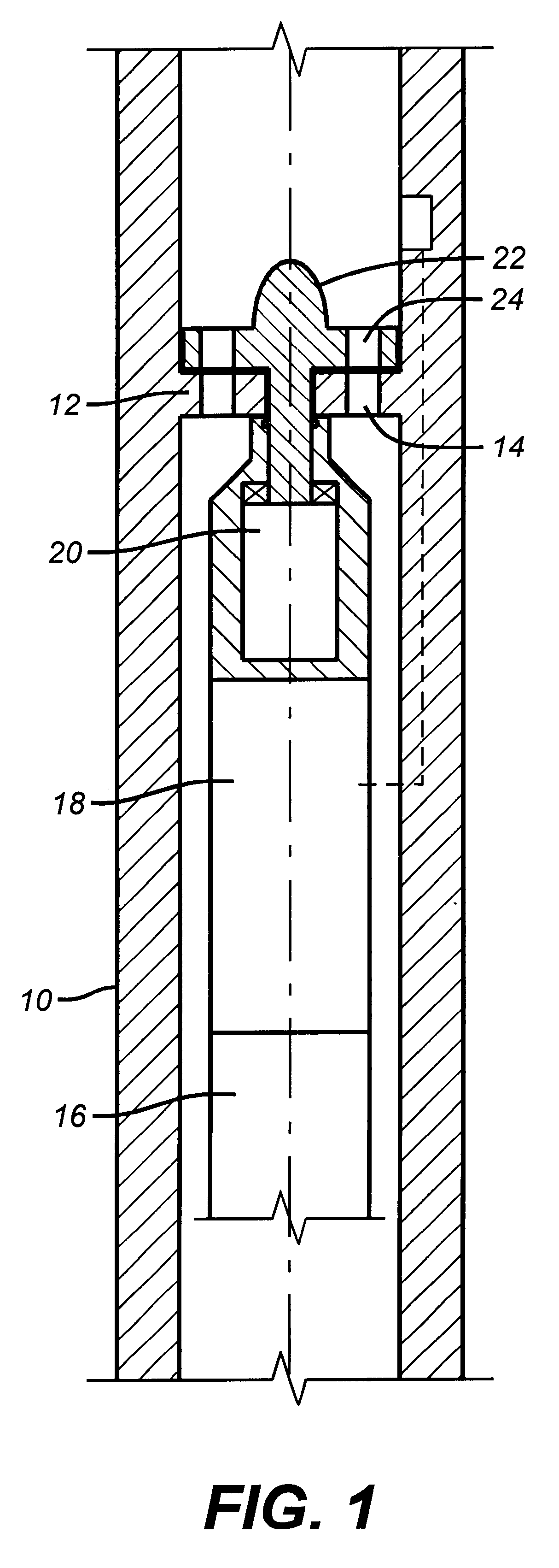
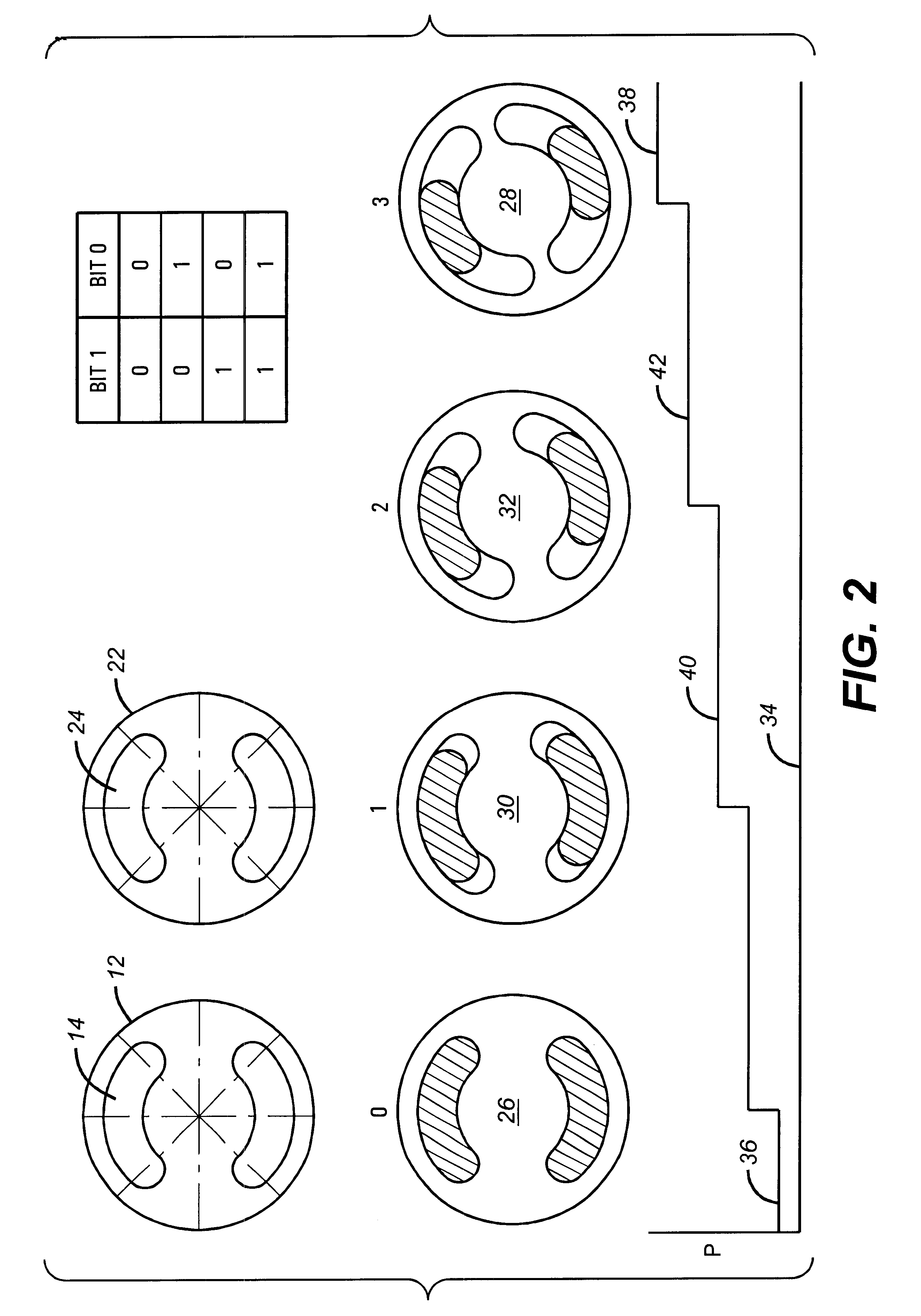
FIG. 1 illustrates a drill collar 10 which is above the drill bit (not shown). Inside the drill collar 10 is a plate 12. Plate 12 has a series of openings 14. The shapes of the openings 14 in plate 12 are more clearly shown in FIG. 2 in plan view.

Supported within the drill collar 10 are downhole instruments 16 which are used for measurement of a variety of conditions downhole of the formation as well as the circulating mud. A processor 18 is mounted adjacent the instruments 16. One of the many functions of the processor 18 is to control the motor 20. Motor 20 is connected directly to plate 22, which is also shown in FIG. 2. Plate 22 has a series of openings 24 which, in the preferred embodiment, match the openings 14 of plate 12. The openings 14 and 24 are preferably crescent-shaped, but other configurations can be used without departing from the spirit of the invention. Motor 20 can orient plate 22 in different positions with respect to the fixed plate 12. FIG. 2 shows, from left t...


PUM


Abstract

A telemetry system involving a shear-type mud pulser valve as the preferred embodiment is described. The control system includes a motor driver for the mud pulser which, in essence, moves one movable plate with respect to a stationary plate to create openings of various sizes. Pressure is sensed uphole of the pulser valve and is compared in real time to the desired pressure pulse amplitude. By allowing different relative rotational positions of the rotatable plate with respect to the stationary plate, different amplitudes can be achieved to further enhance the transmission of data to the surface. The control system compensates for wear in the mud pulser valve itself as well as drastic changes in mud flow and pressure. The configuration is simple and not prone to fouling from grit or other particles in the mud. The system is capable of creating an initial baseline array of a variety of pulse amplitudes, and thereafter providing the required relative rotation between the stationary and rotatable plates so as to be able to duplicate the baseline pulse amplitudes despite changes in the valve condition or in the flowing conditions of the mud.

Description

FIELD OF THE INVENTIONThe field of this invention relates to telemetry systems for transmitting data from downhole drilling assemblies to the surface, and more particularly to a mud-pulsing valve and control system which can generate multi-level signals by producing a variety of pressure amplitude levels so that the quantity of data encoded or the number of bits transmitted can be increased without increasing the frequency of the transmitted signal.BACKGROUND OF THE INVENTIONMeasurement-While-Drilling (MWD) or Logging-While-Drilling (LWD) applications use a mud-pulse system of telemetry to create acoustic signals in the drilling fluid that is circulated under pressure through the drillstring during drilling operations. Information acquired by downhole sensors is transmitted by suitably timing the formation of pressure pulses in the mud stream. This information is received and decoded by a pressure transducer and computer at the surface. Typically, these systems have involved a valve...

Claims


Application Information

Patent Timeline
Patent Type & Authority Patents(United States)
IPC IPC(8): E21B47/12E21B47/18
CPCE21B47/187E21B47/24
Inventor SEYLER, TERRY A.WISLER, MACMILLAN M.
Owner BAKER HUGHES INC
Why Eureka
Try Eureka