Electronic part, dielectric resonator, dielectric filter, duplexer, and communication device comprised of high TC superconductor

a superconductor and dielectric filter technology, applied in the direction of superconductors/hyperconductors, resonators, electrical equipment, etc., can solve the problems of loss increase due to edge effect, dielectric resonator quality, and quality of superconductor formed near the edge where two neighboring surfaces m

Inactive Publication Date: 2002-10-22
MURATA MFG CO LTD
View PDF5 Cites 63 Cited by
  • Summary
  • Abstract
  • Description
  • Claims
  • Application Information

AI Technical Summary

Benefits of technology

FIG. 9 is a perspective view of a conventional dielectric resonator.

Problems solved by technology

Further, in a microstrip-line filter composed of stripline electrodes formed on a dielectric substrate by using a superconductor thin film, when the input power is increased, the loss increases due to the edge effect.
However, there is a problem, in that the quality of the superconductor formed in the vicinity of the edge where two neighboring surfaces join deteriorates in the conventional dielectric resonator.
It has been found that the surface resistance of the superconductor is greatly affected by the morphology (geometrical factors such as the size and shape of crystal grains, arrangement of crystal grains, etc.), and it is easy to realize conditions which reduce the surface resistance of the superconductor formed on a flat area, but it is difficult to reduce the surface resistance of the superconductor formed in the vicinity of the edge.
Therefore, in the conventional dielectric resonator, the surface resistance of the superconductor formed in the vicinity of the edge increases, and as a result it is difficult to increase the unloaded Q of the dielectric resonator.
Further, generally the mechanical strength of superconductors is low, and another problem is that the superconductor formed in the vicinity of the edge of the dielectric resonators peels off or chips off and the reliability is decreased.

Method used


Image

  • Electronic part, dielectric resonator, dielectric filter, duplexer, and communication device comprised of high TC superconductor
  • Electronic part, dielectric resonator, dielectric filter, duplexer, and communication device comprised of high TC superconductor
  • Electronic part, dielectric resonator, dielectric filter, duplexer, and communication device comprised of high TC superconductor

Examples


second embodiment

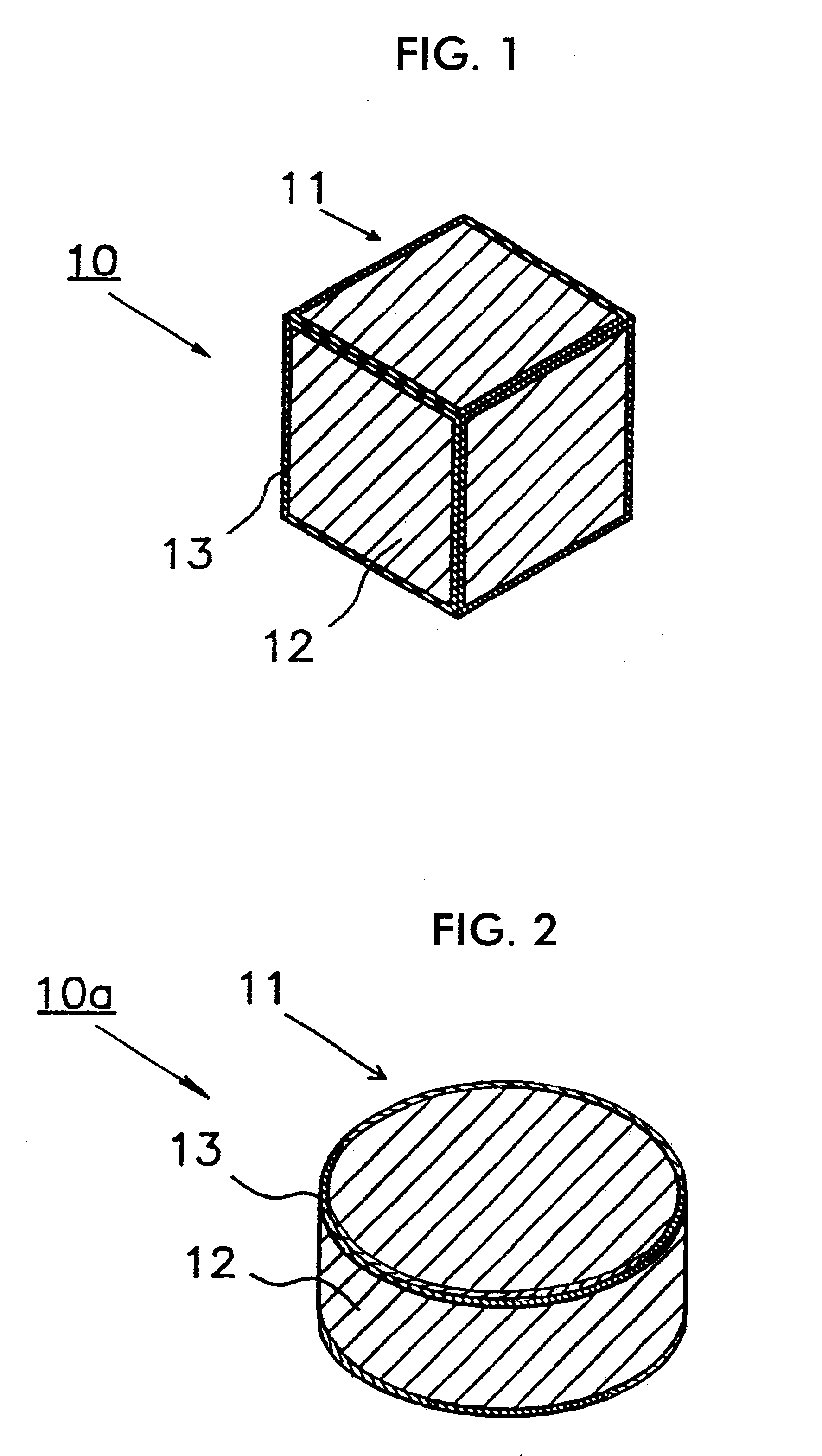
Next, a dielectric resonator of the present invention is explained with reference to FIG. 2. FIG. 2 is a perspective view of a dielectric resonator of the present invention.

As shown in FIG. 2, the dielectric resonator 10a of the present embodiment is composed of a dielectric body 11 of Ba(Sn, Mg, Ta)O.sub.3 system, a superconductor 12 of a thick superconducting film of 2223 phase of Bi system formed on all the external surface of the dielectric body 11, and a metal electrode 13 of silver formed around the edge. The dielectric body 11 is in a cylindrical shape which is 23 mm in diameter and 10 mm in height, and here the edge portions are defined to be the boundary portion between the upper surface and the surrounding side surface and the boundary portion between the lower surface and the surrounding side surface. In the dielectric resonator 10a of such a composition, unloaded Q is nearly 30,000 under the conditions of 2 GHz and 70 K, which is about the same as in the dielectric reson...

fifth embodiment

Further, a dielectric filter of the present invention is explained with reference to FIG. 5. FIG. 5 is an exploded perspective view of a dielectric filter of the present embodiment. Further, as the band-stop filters are the same as in the previous embodiment, their explanation is omitted.

As shown in FIG. 5, the dielectric filter 20a of the present embodiment is composed in part of a band-stop filter 20a1 and in part of a bandpass filter 20a2. The bandpass filter 20a2 is composed of two dielectric resonators 25 placed in parallel, and each of the dielectric resonators 25 is constructed by arranging a dielectric body 26 in a flat shape mounted on a support 18 in a sealed case 27. Regarding the dielectric resonator 25 having such a construction, each of the resonators 25 functions as a triple-mode resonator having three resonance modes and therefore, the bandpass filter 20a2 functions as a six stage bandpass filter in total, having a pair of input-output loops 28, and a coupling loop 2...

sixth embodiment

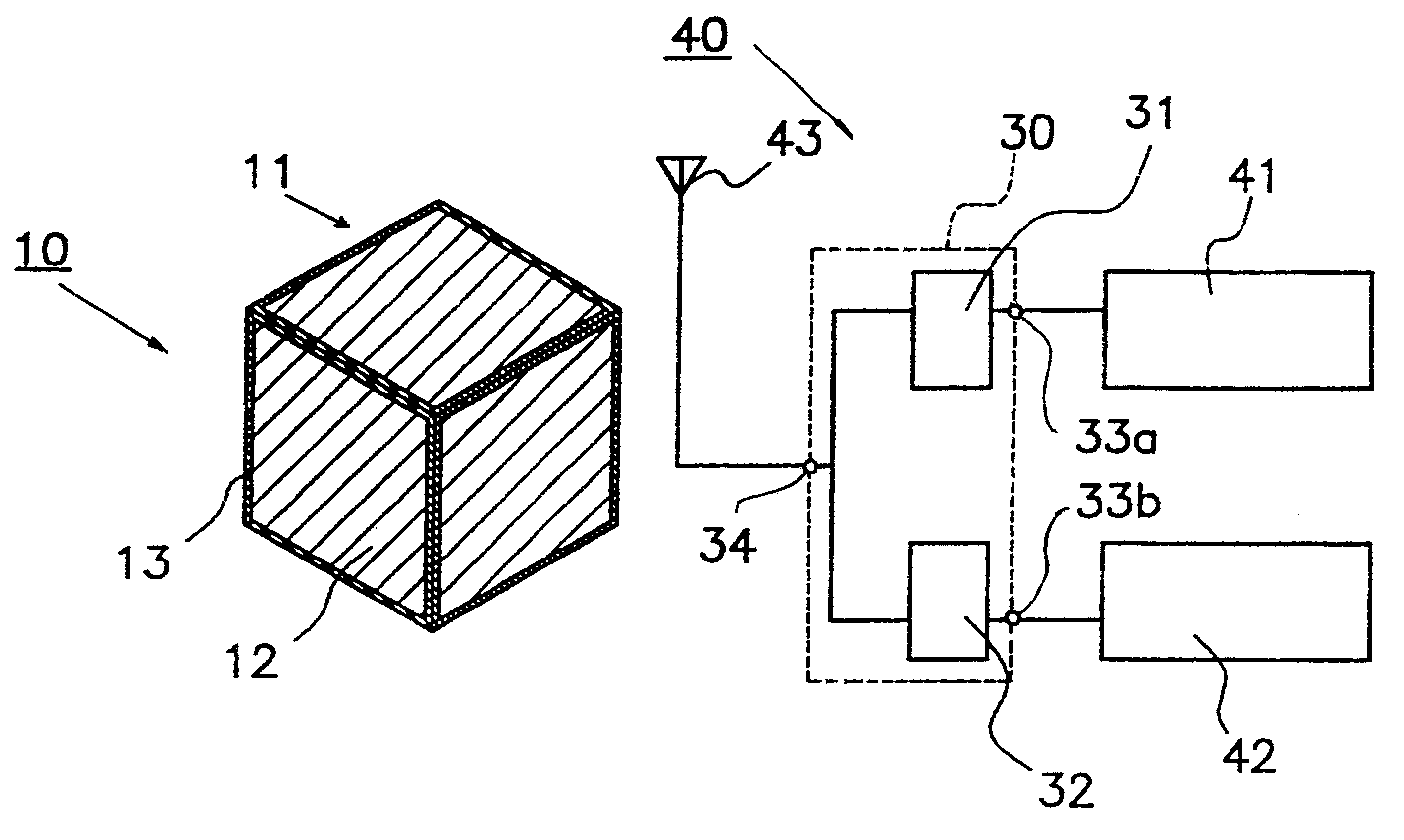
Further, a duplexer of the present invention is explained with reference to FIG. 6. FIG. 6 is a schematic illustration of a duplexer of the present embodiment.

As shown in FIG. 6, the duplexer 30 of the present embodiment is composed of a transmission filter 31 and reception filter 32, and input-output connecting terminals 33a and 33b are formed on the input side of the transmission filter 31 and output side of the reception filter 32. Further, the output side of the transmission filter 31 and input side of the reception filter 32 are combined at an antenna connecting terminal 34. The transmission filter 31 and reception filter 32 in this duplexer 30 are the dielectric filter 20a of the fifth embodiment shown in FIG. 5. Only a signal in one fixed frequency band passes through the transmission filter 31, and only a signal in c band passes through the reception filter 32.


PUM

PropertyMeasurementUnit
thicknessaaaaaaaaaa
dihedral angleaaaaaaaaaa
diameteraaaaaaaaaa

Abstract

In a dielectric resonator, a superconductor is formed on two neighboring surfaces of a cubic dielectric body, and the superconductors formed on each two neighboring surfaces are connected by a silver electrode formed in the vicinity of the edge where the neighboring two surfaces join.

Description

1. Field of the InventionThe present invention relates to a dielectric resonator, dielectric filter, duplexer, communication device, and electronic part with a superconductor formed therein which are usable for example in base stations for microwave- and milliwave-band communication equipment.2. Description of the Related ArtA conventional dielectric resonator is explained with reference to FIG. 9. FIG. 9 is a perspective view of a conventional dielectric resonator.As shown in FIG. 9, the conventional dielectric resonator 110 is composed of a dielectric body 111 in a cubic shape measuring 22 mm on each edge which is made up of a dielectric material of, for example, a Ba(Sn, Mg, Ta)O.sub.3 system. A superconductor 112 is formed on the entire external surface of the dielectric body 111 by screen printing, that is, a thick superconducting film of, for example, 2223 phase of a Bi system. In the dielectric resonator 110 having such composition, the superconductor 112 formed all over the ...

Claims


Application Information

Patent Timeline
Patent Type & Authority Patents(United States)
IPC IPC(8): H01P7/10H01P1/20H01P1/205H01P1/213
CPCH01P1/2053H01P7/10H01P7/105Y10S505/70Y10S505/886
Inventor KINTAKA, YUJIMATSUI, NORIFUMI
Owner MURATA MFG CO LTD
Why Eureka
Try Eureka