
Method and system for data processing system self-synchronization

a data processing system and data processing technology, applied in the field of data processing systems, can solve the problems of the output signal of the pll circuit to lose lock with the input reference signal, the performance and the output signal of the pll circuit is notoriously sensitive to environmental influences

Inactive Publication Date: 2002-10-22
IBM CORP
View PDF3 Cites 48 Cited by
  • Summary
  • Abstract
  • Description
  • Claims
  • Application Information

AI Technical Summary

Benefits of technology

It is another object of the present invention to provide an improved method and system for improved synchronization of a data processing system's components.

Problems solved by technology

Typically, both the low-pass filter and the voltage control oscillator (VCO) of a PLL circuit employ analog components, and because of these analog components, PLL circuits are notoriously sensitive to environmental influences.
In addition, there are also other sources that affect the performance of a PLL circuit, for example, a noisy or missing input reference signal, a noisy or missing output signal, a noisy or insufficient power supply to the PLL circuits, or extraneous noise picked up by the PLL circuit.
Quite often, any one or more of the above factors may lead the PLL circuit output signal to lose lock with the input reference signal.
With high speed clocks distributed to multiple chips within a system it is difficult to guarantee synchronization.
Chips processes may become chaotic.
Presently, it is difficult to provide a method or system which provides this level of synchronization without a PLL.

Method used


Image

  • Method and system for data processing system self-synchronization
  • Method and system for data processing system self-synchronization
  • Method and system for data processing system self-synchronization

Examples


Embodiment Construction

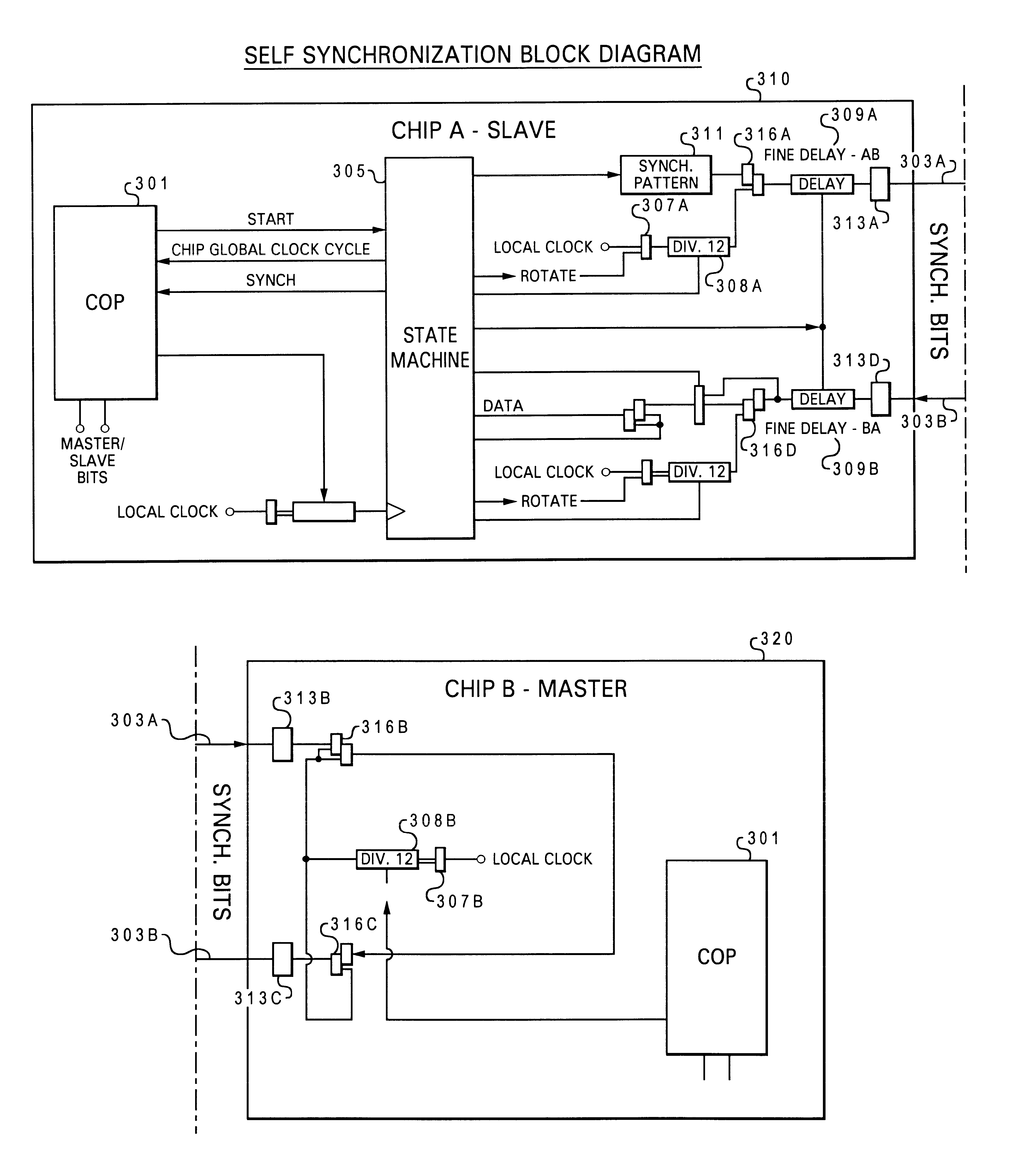
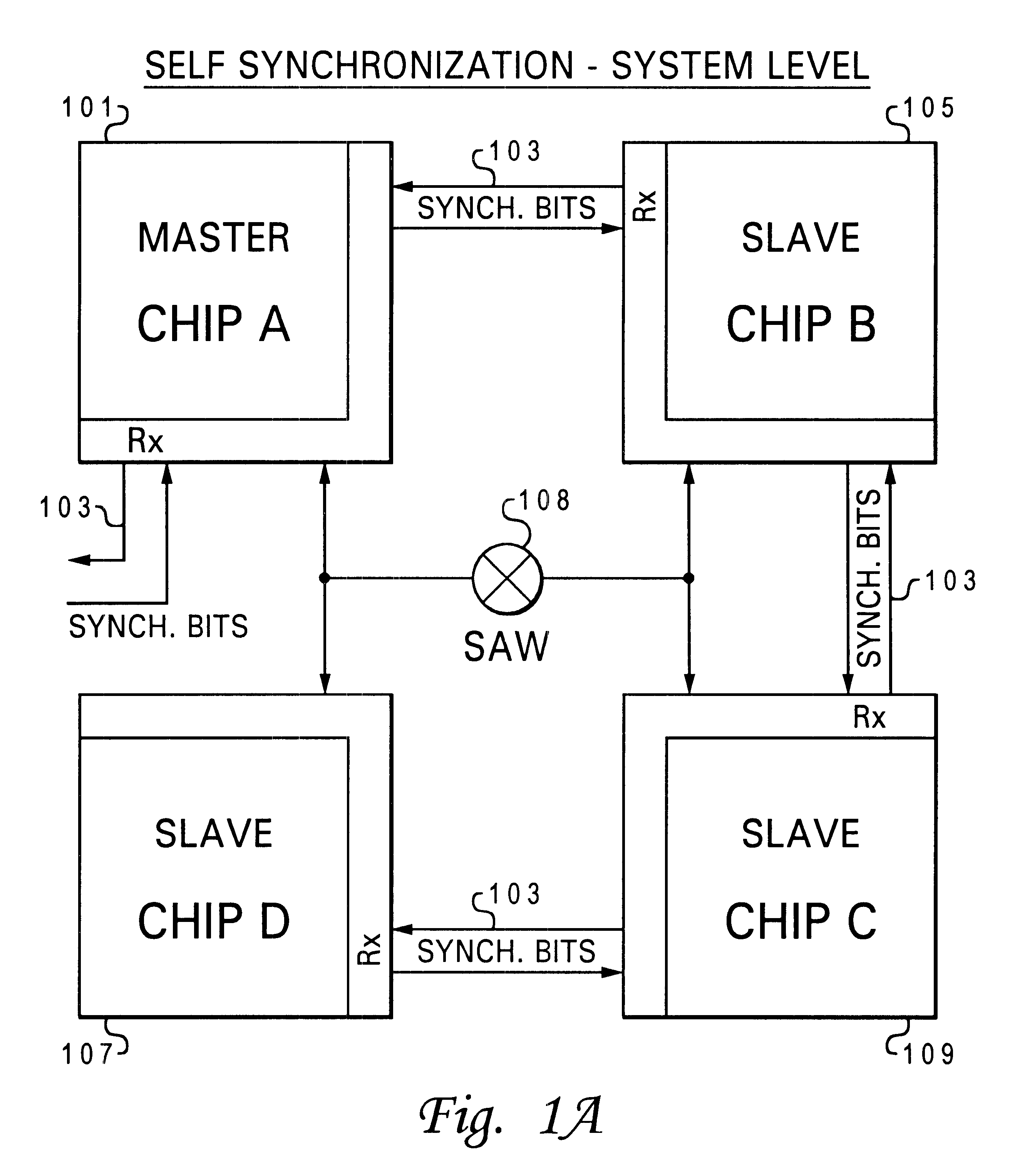
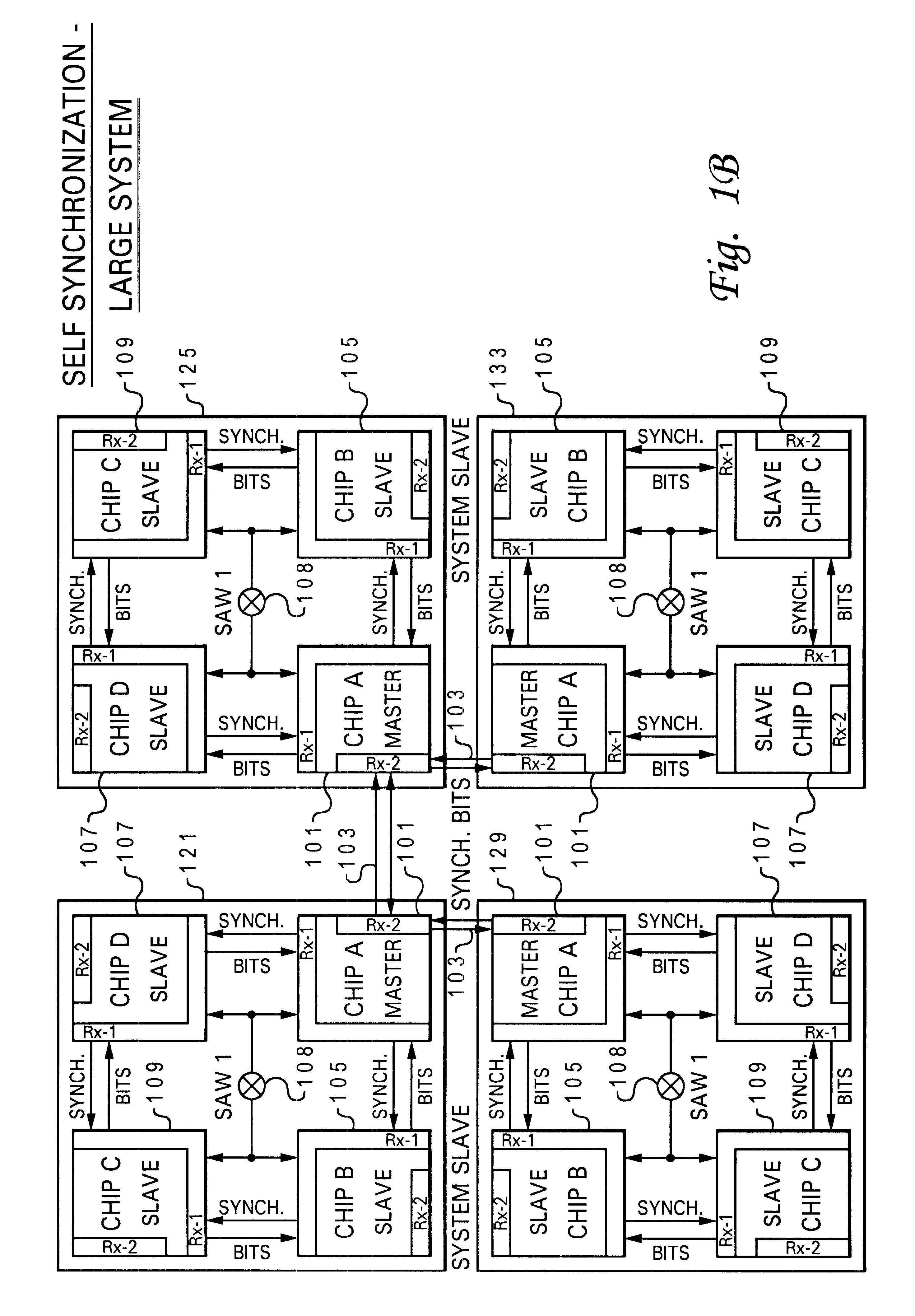
This invention allows a self-synchronization of chips of a data processing system. FIG. 1A depicts a block diagram of the simplified topology of a group of components utilized within the invention. In the preferred embodiment, two types of chips exist, a master chip 101 coupled to a number of servant chips, specifically chip B 105, chip C 109 and chip D 107. Servant chip operates as a "slave" chip and both terms are used interchangably throughout. Master chip 101 is similar to servant chips but has been designated to be the control chip of the group. Each slave chip in the group is configured to share synchronization (sync) bits 103 with master chip 101 either directly or indirectly. Each group of chips in turn are connected to a high speed surface acoustic wave oscillator ("SAW") 108 sent to all the chips. As is shown, sync bits 103 also connect master chip 101 to other groups of chips as depicted in FIG. 1B. Notably in this embodiment each group 121, 125, 129, and 133 includes the...


PUM


Abstract

A method and system for dynamic synchronization of a data processing system processor chips. One of a plurality of chips is designated as a primary chip and all other chips as secondary chips. The clock phase of the chips are synchronized utilizing the primary chip's clock phase as a reference clock phase for the secondary chips.

Description

1. Technical FieldThe present invention relates to data processing systems, and in particular to a method and system for improved synchronization of a data processing system's components. Still more particularly, the present invention relates to a method and system for dynamic self-synchronization of data processing system components.2. Description of the Prior ArtSynchronization among chip components of a data processing system is an important aspect of system performance. When chips are synchronized, they are able to execute similarly. However, if chips are not synchronized, then the same instruction takes place on different chips at different times. In present day data processing, it is desired to have systems which are deterministic, particularly for utilization with logical functions and flow which require orderly flow. Presently, most synchronization is handled via phase locked loop circuitry.Phase-locked loop ("PLL") circuits are electronic circuits utilized for locking an ou...

Claims


Application Information

Patent Timeline
IPC IPC(8): G06F1/12G06F1/10
CPCG06F1/10G06F1/12
Inventor DREPS, DANIEL MARKFERRAIOLO, FRANK DAVIDKOLOR, DANIEL JOHNMCCREDIE, BRADLEY
Owner IBM CORP
Learn More