Deposit accepting and storage apparatus and method for automated banking machine

a technology of automatic banking machine and deposit acceptance, which is applied in the directions of atm details, instruments, transportation and packaging, etc., can solve the problems of user's frequent "bad check" fee, possible damage to printing mechanism or check, and increase the risk of damage to the printing mechanism or check. , to achieve the effect of reducing the likelihood of interference with the acceptance of deposits

Inactive Publication Date: 2002-11-05
DIEBOLD NIXDORF
View PDF9 Cites 114 Cited by
  • Summary
  • Abstract
  • Description
  • Claims
  • Application Information

AI Technical Summary

Benefits of technology

In response to the host computer determining that the check cashing transaction is suitable to be carried forward, an authorization message is returned from the host computer to the ATM. The ATM operates responsive to the authorization message to cause the check to be moved through the transport section past the printing mechanism. The printing mechanism operates to print data on the check. This data may indicate that the check has been cancelled as well as indicate the particular account of the user to which the check has been credited. In the exemplary embodiment the printing mechanism operates in the manner previously discussed to move into position in response to sensing the check adjacent thereto. This again minimizes the risk of damage to the printing mechanism or the check.
The computer also operates to control the deposit holdin

Problems solved by technology

Many automated banking machines accept deposits from users in envelopes Because the contents of the envelope is not verified at the time of deposit, the user's account cannot be credited for the deposit until the envelope is retrieved from the machine and the contents thereof verified.
Delays in crediting a user's account may be experienced due to delays in removing deposits from machines, as well as the time it takes to review deposited items and enter appropriate credits.
If the deposited items include instruments such as checks, further delays may be experienced.
In addition the user commonly incurs a "bad check" fee due to the cost associated with the institution having to handle a dishonored deposit.
All of these complications may result in delays and inconvenience to the user.
Another risk associated with conventional depositories in automated banking machines is that deposited items may be misappropriated.
Because deposited checks and other instruments are not cancelled at the time of receipt by the automated banking machine, they may be stolen from the machine and cashed by unauthorized persons.
Alternatively persons responsible for transporting items from the machine or persons responsible for verifying the items may misappropriate deposited instruments and currency.
Alternatively the handling required for transporting and verifying the contents of deposits may result in deposited instruments being lost.
Such circumstances can result in the user not receiving proper credit for deposited items.
While automated deposit accepting and processing devices provide many advantages and benefits, existing devices also have drawbacks.
One drawback is that instruments must be precisely aligned for purposes of reading micr coding or other indicia which is included on the instrument.
A further drawback associated with some existing devices is that they are required to turn and reorient the deposited instrument.
The mechanisms for doing this can be complex.
Such complex mechanisms may encounter reliability problems due to the precise tolerances that must be maintained.
Further difficulty is added by the f

Method used


Image

  • Deposit accepting and storage apparatus and method for automated banking machine
  • Deposit accepting and storage apparatus and method for automated banking machine
  • Deposit accepting and storage apparatus and method for automated banking machine

Examples


Embodiment Construction

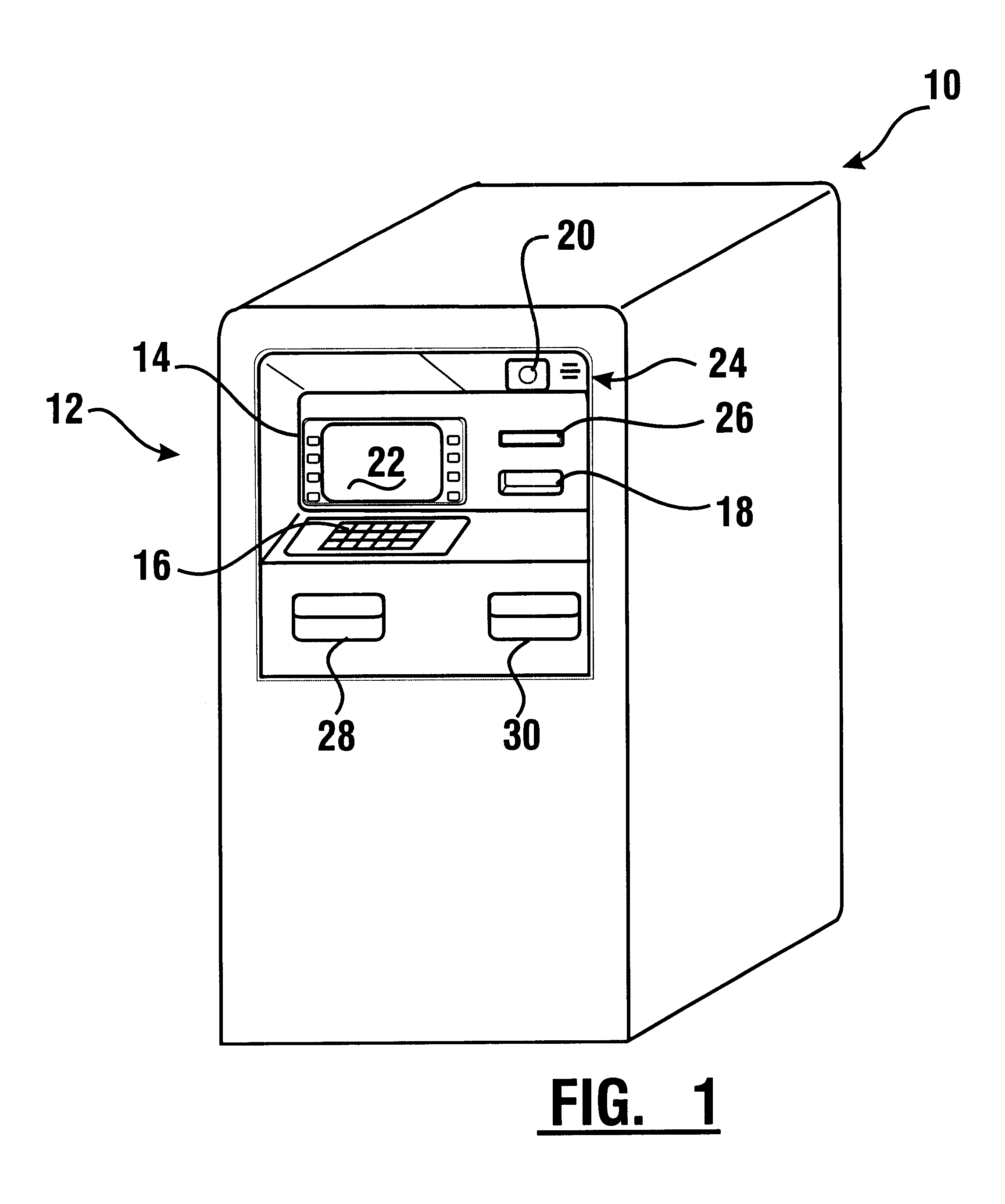
Referring now to the drawings and particularly to FIG. 1, there is shown therein an exemplary embodiment of an automated banking machine 10 of the present invention which includes an exemplary deposit accepting apparatus and which performs an exemplary method of operation. Automated banking machine 10 is an ATM. However it should be understood that the present invention may be used in connection with various types of automated banking machines and devices of other types. Automated banking machine 10 includes a user interface generally indicated 12. User interface 12 includes input and output devices. In the exemplary embodiment the input devices include a plurality of function buttons 14 through which a user may provide inputs to the machine. The exemplary input devices further include a keypad 16 through which a user may provide numeric or other inputs. A further input device in this exemplary embodiment includes a card reader schematically indicated 18. Card reader 18 may be of th...


PUM


Abstract

An automated banking machine (10) includes a deposit accepting apparatus (44) which is capable of accepting and authenticating instruments, as well as accepting envelopes deposited into the machine by a user. A transport section (46) is operative to engage and transport deposited items selectively from an inlet (48) to an outlet (50). A deposit holding module (90) includes compartments (98, 106) which are operative to hold different types of deposits. The machine operates to selectively move a compartment into communication with the outlet based on the particular type of item being deposited. The depository apparatus is further operative to acquire image and magnetic profile data from deposited instruments, to manipulate the image and profile data and to analyze and resolve characters in selected areas thereof. The data from deposited instruments is used for determining if a user is authorized to conduct certain requested transactions at the machine.

Description

This invention relates to automated banking machines. Specifically this invention relates to devices and systems which receive deposits of individual sheets such as checks and other instruments, as well as items such as envelopes, into an automated banking machine.Automated banking machines are known in the prior art. Automated banking machines are commonly used to carry out transactions such as dispensing cash, checking account balances, paying bills and / or receiving deposits from users. Other types of automated banking machines may be used to purchase tickets, to issue coupons, to present checks, to print scrip and / or to carry out other functions either for a consumer or a service provider. For purposes of this description any device which is used for carrying out transactions involving transfers of value shall be referred to as an automated banking machine.Automated banking machines often have the capability of accepting deposits from users. Such deposits may include items such a...

Claims


Application Information

Patent Timeline
IPC IPC(8): G07D11/00G07F19/00
CPCG07D11/009G07F19/20G07F19/202
Inventor MONTROSS, CRAIG A.BROWN, MARTIN J.GALLOWAY, TODDBARNETT, ROBERT W.RYAN, MIKEKAY, JAMES R.WARD, MARK A.PETERS, DAVID A.DAY, ALAN
Owner DIEBOLD NIXDORF
Why Eureka
Try Eureka