

Surface configuration measuring method
a surface configuration and measuring method technology, applied in the direction of mechanical measurement arrangements, mechanical roughness/irregularity measurements, instruments, etc., can solve the problems of natural degradation of measurement accuracy, enormous total work time,
- Summary
- Abstract
- Description
- Claims
- Application Information
AI Technical Summary
Problems solved by technology
Method used
Image

Examples
first embodiment
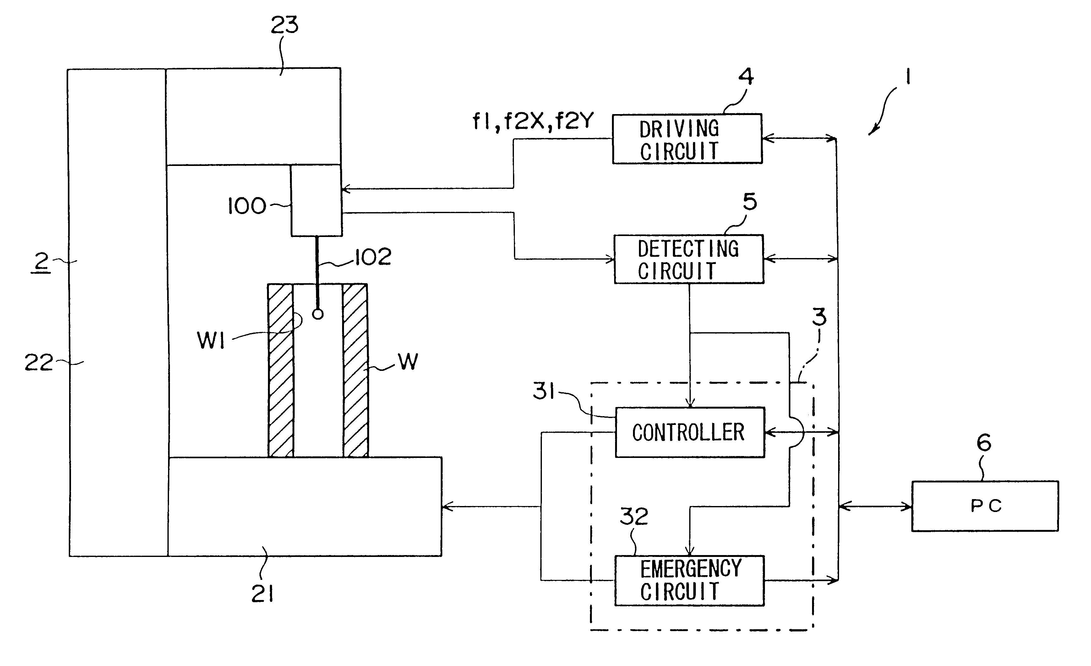
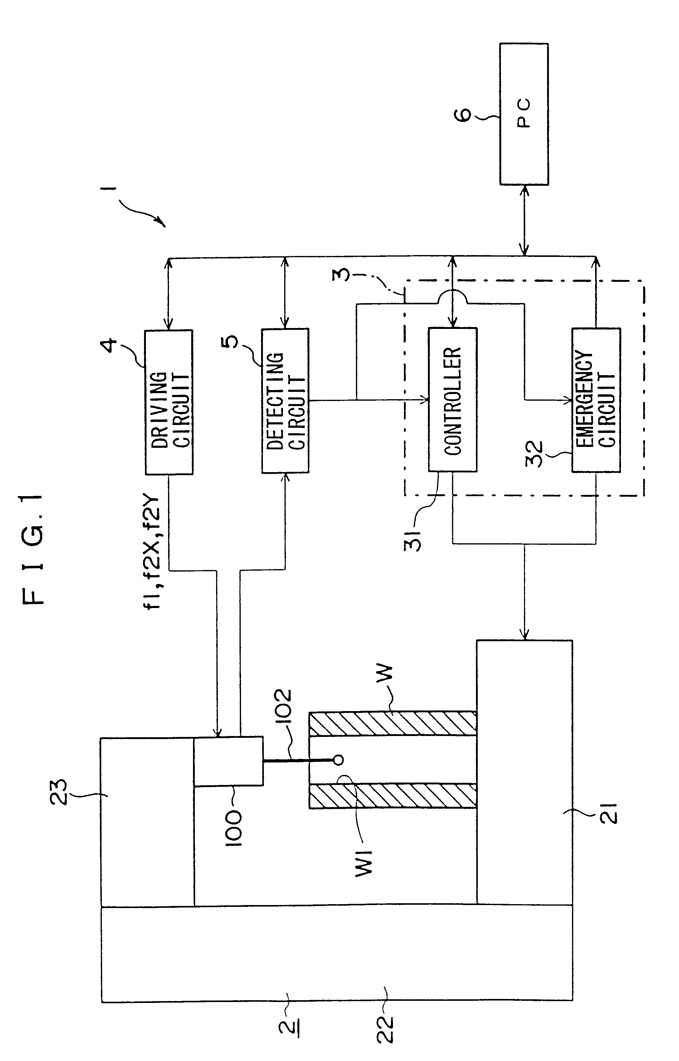
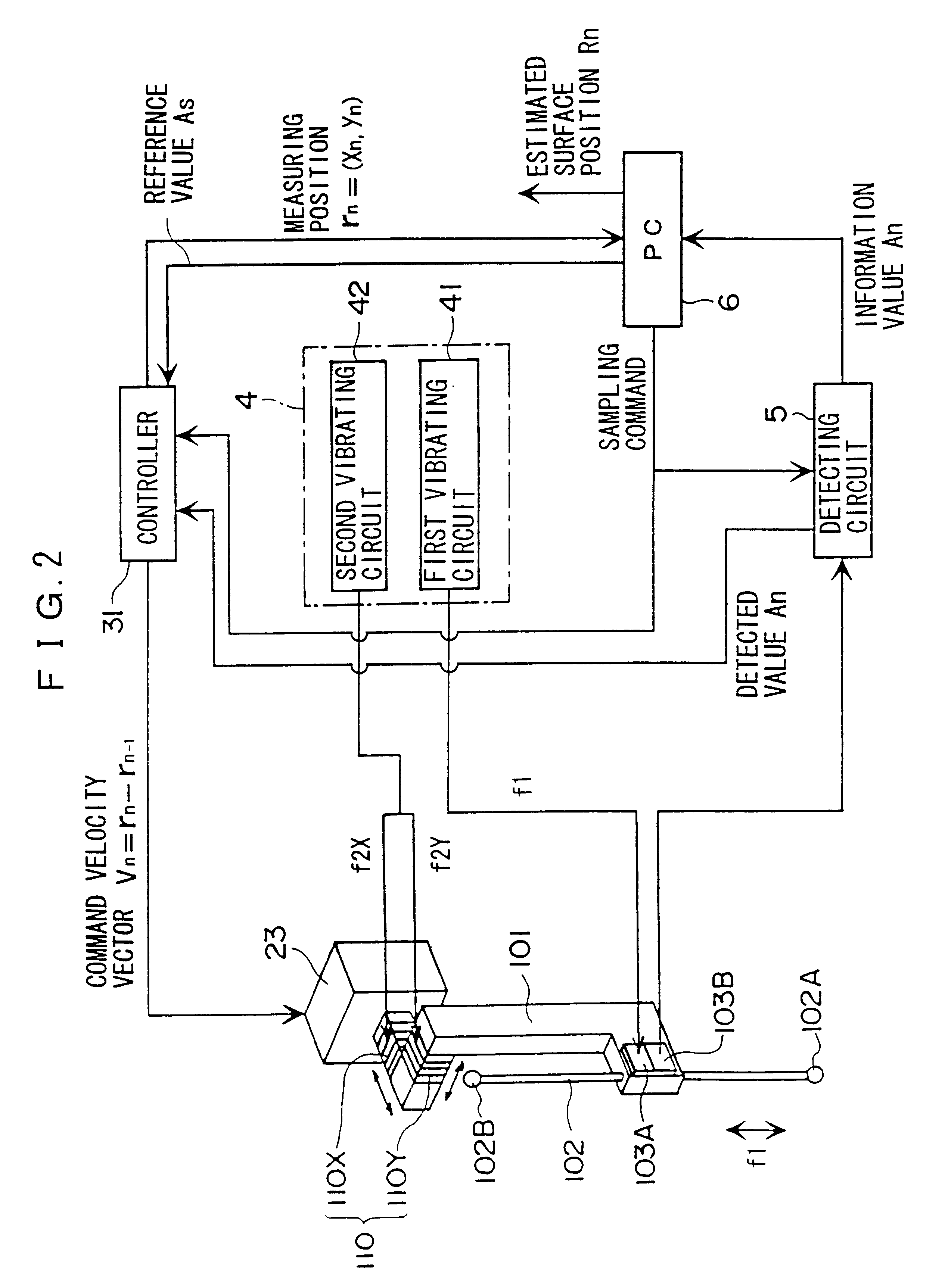
FIGS. 1 and 2 show an inside-outside measuring machine installed to practice the surface configuration measuring method according to the present invention.
The inside-outside measuring machine 1 has a measuring machine body 2, a control circuit 3, a driving circuit 4, a detecting circuit 5, and a personal computer 6. The driving circuit 4 vibrates the touch signal probe 100 in the axial direction of the stylus and in a direction orthogonal with the axis. The detecting circuit 5 arithmetically processes the electric signal from the detector provided to the stylus and outputs a signal to the control circuit 3. The personal computer 6 outputs a control signal to the control circuit 3 to control the movement of the measuring machine body 2, and arithmetically processes the detected value of the detecting circuit 5 and the controller 31 of the control circuit 3 to evaluate the roundness, etc. of a workpiece W.
The workpiece W is put on the measuring machine body 2 to measure the surface co...
second embodiment
The second embodiment is the same as the above-described first embodiment in the arrangement of the device and scanning steps and differs in the calculation process of the estimated surface position R.sub.n as the final step of the operation steps. Accordingly, only the different calculation step of the estimated surface position R.sub.n will be described below, thus omitting the description of the other common parts.
FIG. 9 shows calculation steps of the estimated surface position R.sub.n according to the present embodiment. Though auxiliary vector h'.sub.n is set as h'.sub.n =r.sub.n+1 -r.sub.n-1 in the above first embodiment, the auxiliary vector h'.sub.n is set as h'.sub.n =r.sub.n -r.sub.n-1 in the present embodiment. Subsequent calculation may be the same as the first embodiment.
According to the second embodiment, since the succeeding measuring position r.sub.n+1 as in the first embodiment is not required, the detection data can be immediately processed arithmetically.
Specifica...
third embodiment
The third embodiment is the same as the above-described first embodiment in the arrangement of the device and scanning steps and differs in the calculation process of the estimated surface position R.sub.n as the final step of the operation process. Accordingly, only the different calculation step of the estimated surface position R.sub.n will be described below, thus omitting description of the other common parts.
FIG. 10 shows calculation steps of the estimated surface position R.sub.n according to the present embodiment. Auxiliary vector h'.sub.n is set as h'.sub.n =r.sub.n+1 -r.sub.n-1 in the above first embodiment, and the auxiliary vector h'.sub.n is set as h'.sub.n =r.sub.n -r.sub.n-1 in the above second embodiment. In contrast thereto, in the present embodiment, a plurality of measurement points adjacent to r.sub.n (r.sub.n-1, r.sub.n, r.sub.n+1, r.sub.n+2 etc.) is selected. An approximate curve C.sub.n is set based on the respective points and a perpendicular is drawn from t...
PUM
 Abstract
Description
Claims
Application Information