
Active solid polymer electrolyte membrane in solid polymer type fuel cell and process for the production thereof

a solid polymer and electrolyte technology, applied in the direction of cell components, final product manufacturing, sustainable manufacturing/processing, etc., can solve the problems of low power generation ability of the fuel cell, degraded power generation ability, and waste of expensive precious metals

Inactive Publication Date: 2002-11-26
HONDA MOTOR CO LTD
View PDF4 Cites 22 Cited by
  • Summary
  • Abstract
  • Description
  • Claims
  • Application Information

AI Technical Summary

Benefits of technology

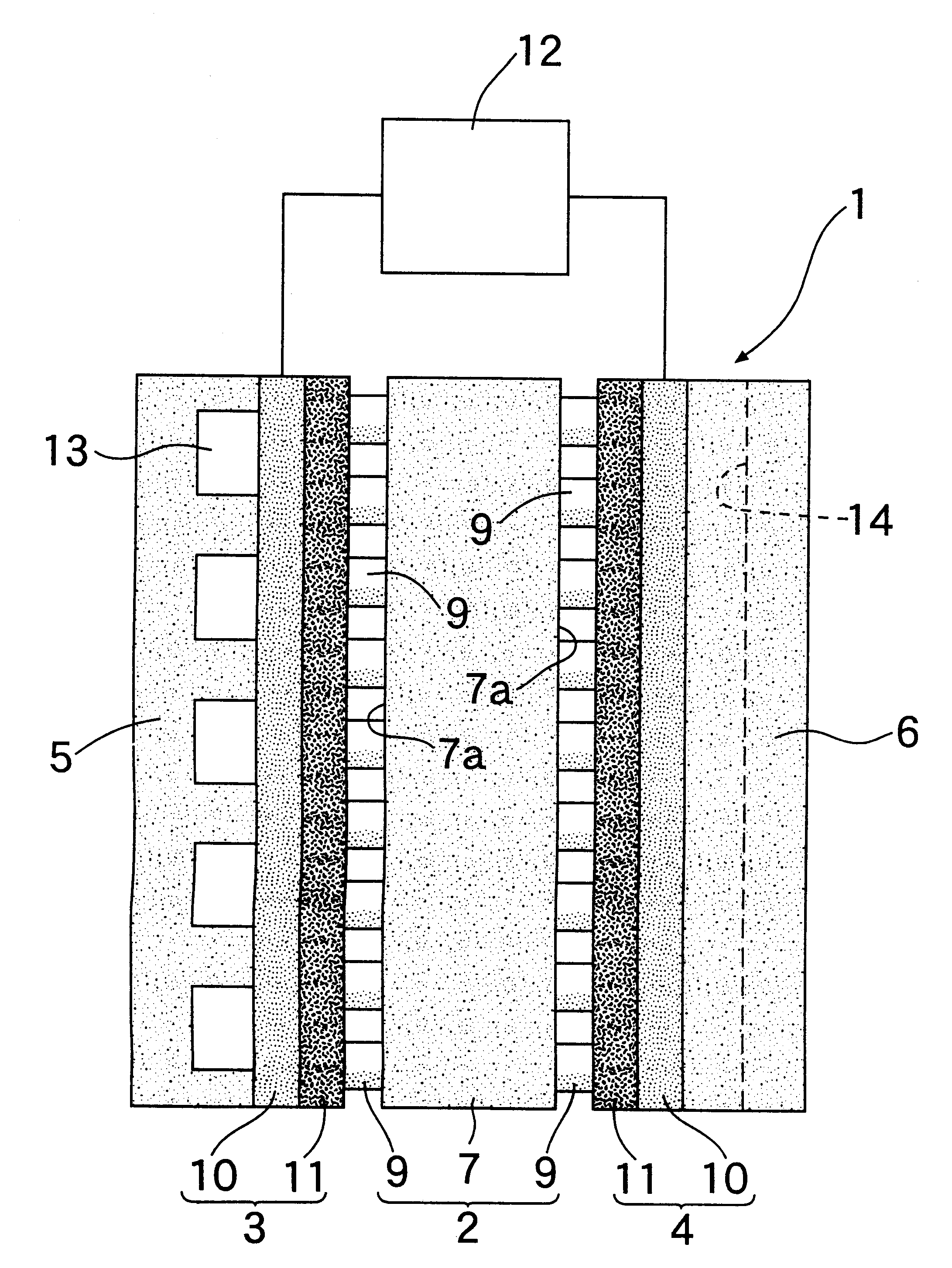
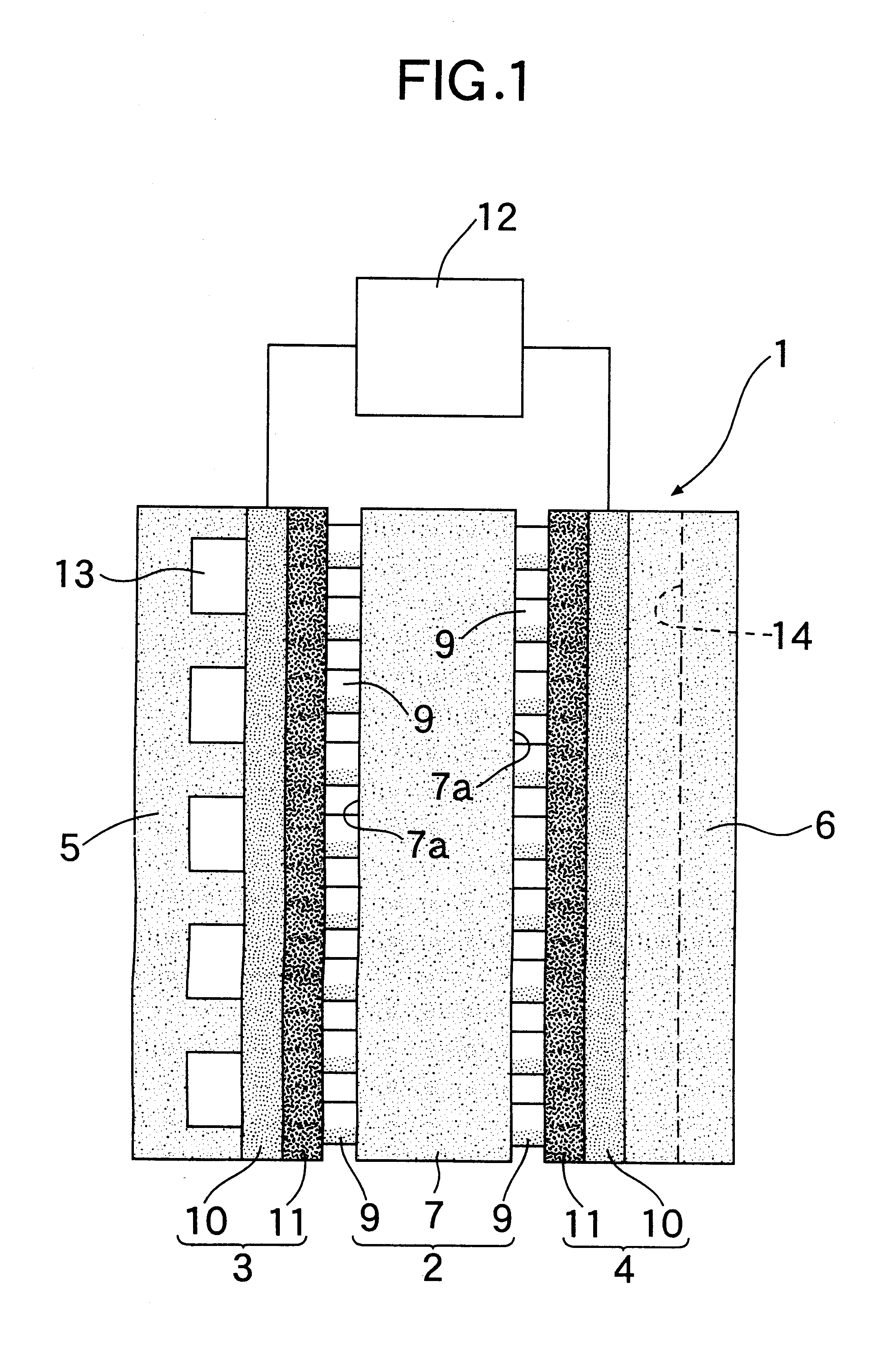
In accordance with the aforementioned arrangement, since the precious metal catalyst particles are present as spots on the surfaces of the aforementioned electrolyte membrane, the conduction of the generated hydrogen ions to the aforementioned electrolyte membrane and the conduction thereof from the electrolyte membrane to the air electrode both become high and association between the hydrogen ions and oxygen is enhanced. Moreover, the area of the three phase interface at which the three elements of precious metal catalyst particle, solid polymer electrolyte membrane and fuel gas come into contact with each other increases. Thus, it becomes possible to reduce the amount of precious metal supported on the aforementioned electrolyte membrane and at the same time increase the efficiency of power generation in the fuel cell.
In accordance with the aforementioned arrangement, since the precious metal catalyst particles are present as spots inside the surface layers of the aforementioned electrolyte membrane, the conduction of the generated hydrogen ions to the aforementioned electrolyte membrane and the conduction thereof from the electrolyte membrane to the air electrode become both high and association between the hydrogen ions and oxygen is enhanced. Moreover, the area of the three phase interface at which the three elements of precious metal catalyst particle, solid polymer electrolyte membrane and fuel gas come into contact with each other increases. It thus becomes possible to reduce the amount of precious metal supported in the aforementioned electrolyte membrane and at the same time increase the efficiency of power generation in the fuel cell.
Furthermore, it is an object of the present invention to provide a production process in which the aforementioned active solid polymer electrolyte membrane can be mass produced.

Problems solved by technology

However, since the conventional precious metal catalyst is formed as a layer, the conduction of the generated hydrogen ions to the solid polymer electrolyte membrane and the conduction from the electrolyte membrane to the air electrode are comparatively low, and the area of the interface at which the three elements of precious metal catalyst, solid polymer electrolyte membrane and fuel gas (hydrogen and air) come into contact with each other, that is to say, the area of the three phase interface, is small and in spite of a large amount of precious metal being supported on the electrolyte membrane the ability of the fuel cell to generate power is low, which is a problem.
When the reduction treatment is effected without carrying out the first washing, free precious metal atoms remain inside the aforementioned electrolyte membrane, and as these precious metal atoms generally do not contribute to the generation of hydrogen ions expensive precious metal is therefore wasted.
When the second washing is not carried out, since residual reducing component interferes with the ionisation of hydrogen the ability to generate power is degraded.

Method used


Image

  • Active solid polymer electrolyte membrane in solid polymer type fuel cell and process for the production thereof
  • Active solid polymer electrolyte membrane in solid polymer type fuel cell and process for the production thereof
  • Active solid polymer electrolyte membrane in solid polymer type fuel cell and process for the production thereof

Examples


embodiment ii

In FIGS. 6 and 7 a cell unit 1 forming a solid polymer type fuel cell comprises an active solid polymer electrolyte membrane 2 (hereinafter in this section termed an active electrolyte membrane), an air electrode 3 and a fuel electrode 4, each of which are in close contact with the surfaces on both the sides of the above-mentioned active electrolyte membrane, and a pair of separators 5, 6 which are in close contact with the above-mentioned two electrodes 3, 4 respectively.

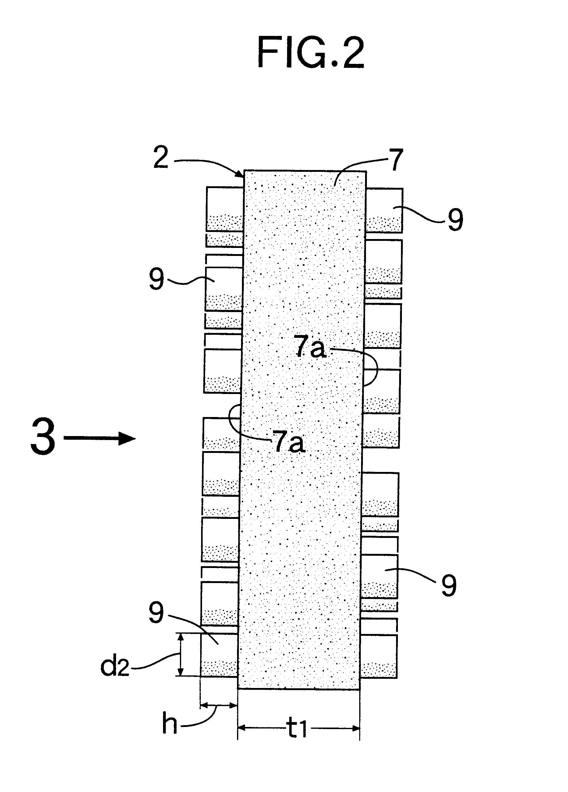
The active electrolyte membrane 2 comprises a solid polymer electrolyte membrane 7 (hereinafter in this section termed an electrolyte membrane) having a thickness to which satisfies the relationship 5 .mu.m.ltoreq.t.sub.1.ltoreq.200 .mu.m, and a plurality of precious metal catalyst particles 9 which are supported inside the surface layers 7b of the aforementioned electrolyte membrane 7 by ion exchange and distributed uniformly throughout the inside of the surface layer 7b thereof. The thickness t.sub.2 of the surfa...


PUM

PropertyMeasurementUnit
thickness t2aaaaaaaaaa
crystallite diameter d1aaaaaaaaaa
heightaaaaaaaaaa

Abstract

An active solid polymer electrolyte membrane in a solid polymer type fuel cell comprises a solid polymer electrolyte membrane and a plurality of precious metal catalyst particles supported on the surfaces of the aforementioned solid polymer electrolyte membrane by ion exchange and distributed uniformly over the surfaces thereof. In accordance with the use of this active solid polymer electrolyte membrane the ability to generate power can be enhanced.

Description

1. Field of the InventionThe present invention relates to active solid polymer electrolyte membranes in solid polymer type fuel cells and a process for the production thereof.2. Description of the Prior ArtWith regard to active solid polymer electrolyte membranes of this type in the art, those in which a precious metal catalyst is supported on the surface of a solid polymer electrolyte membrane by a sputtering method are known.However, since the conventional precious metal catalyst is formed as a layer, the conduction of the generated hydrogen ions to the solid polymer electrolyte membrane and the conduction from the electrolyte membrane to the air electrode are comparatively low, and the area of the interface at which the three elements of precious metal catalyst, solid polymer electrolyte membrane and fuel gas (hydrogen and air) come into contact with each other, that is to say, the area of the three phase interface, is small and in spite of a large amount of precious metal being ...

Claims


Application Information

Patent Timeline
Patent Type & Authority Patents(United States)
IPC IPC(8): H01M8/10
CPCH01M8/1004Y10T29/49115Y02E60/521H01M2300/0082Y02P70/50Y02E60/50
Inventor FUKUDA, KAORUTERADA, KAZUHIDESAITO, NOBUHIRO
Owner HONDA MOTOR CO LTD
Learn More