Multistage gas generator for air bag and air bag apparatus

Inactive Publication Date: 2002-12-10
DAICEL CHEM IND LTD
View PDF109 Cites 53 Cited by
  • Summary
  • Abstract
  • Description
  • Claims
  • Application Information

AI Technical Summary

Problems solved by technology

However, these above conventional gas generators are not a multistage gas generator for an air bag with a simple structure which can be manufactured easily, suppressing the entire size of the container (housing).
In this case, remaining ignition means and gas generating means which were not actuated cause inconvenience at the time of later disposal or damping.
If the cent

Method used


Image

  • Multistage gas generator for air bag and air bag apparatus
  • Multistage gas generator for air bag and air bag apparatus
  • Multistage gas generator for air bag and air bag apparatus

Examples


embodiment

of AIM 1

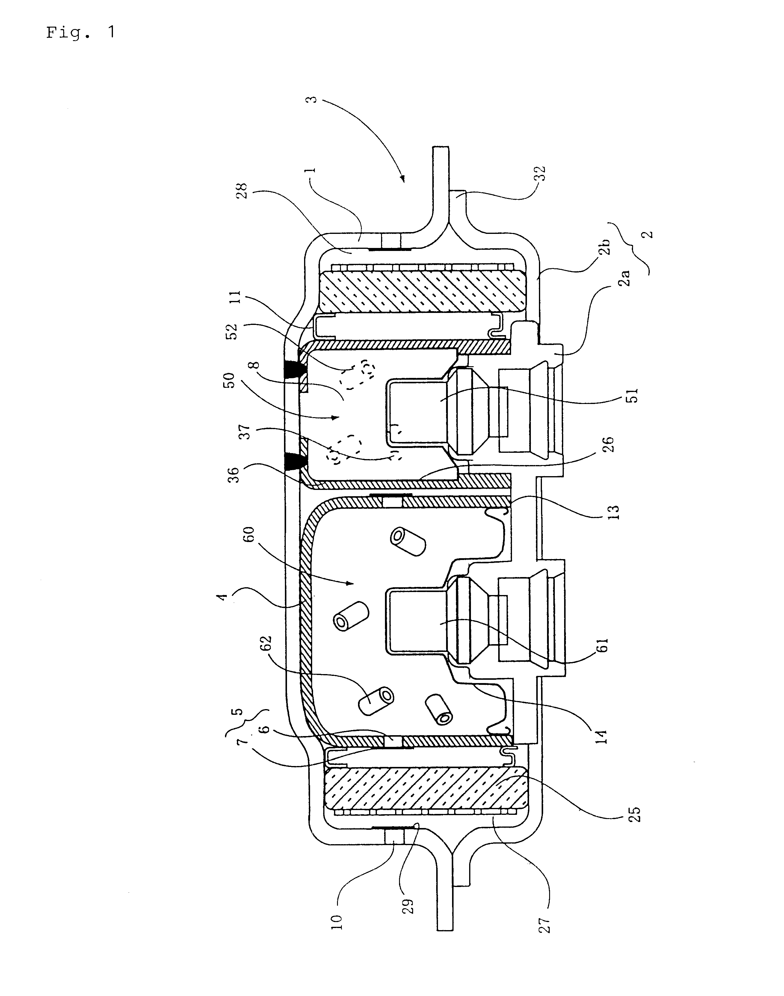
FIG. 28 is a vertical cross sectional view showing another embodiment of the gas generator for an air bag of the present invention. The gas generator shown in this figure has a structure suitable to be disposed on a driver side.

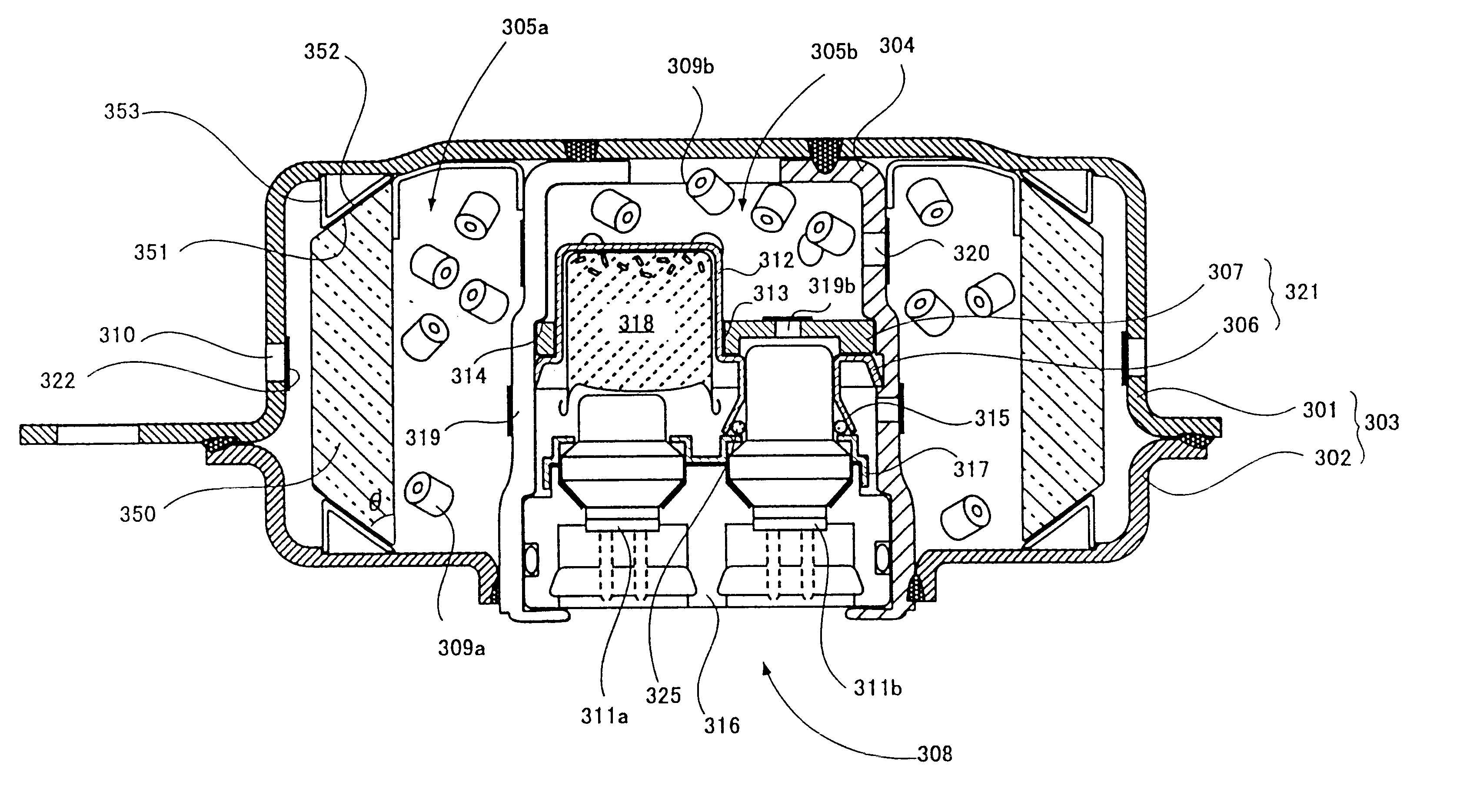
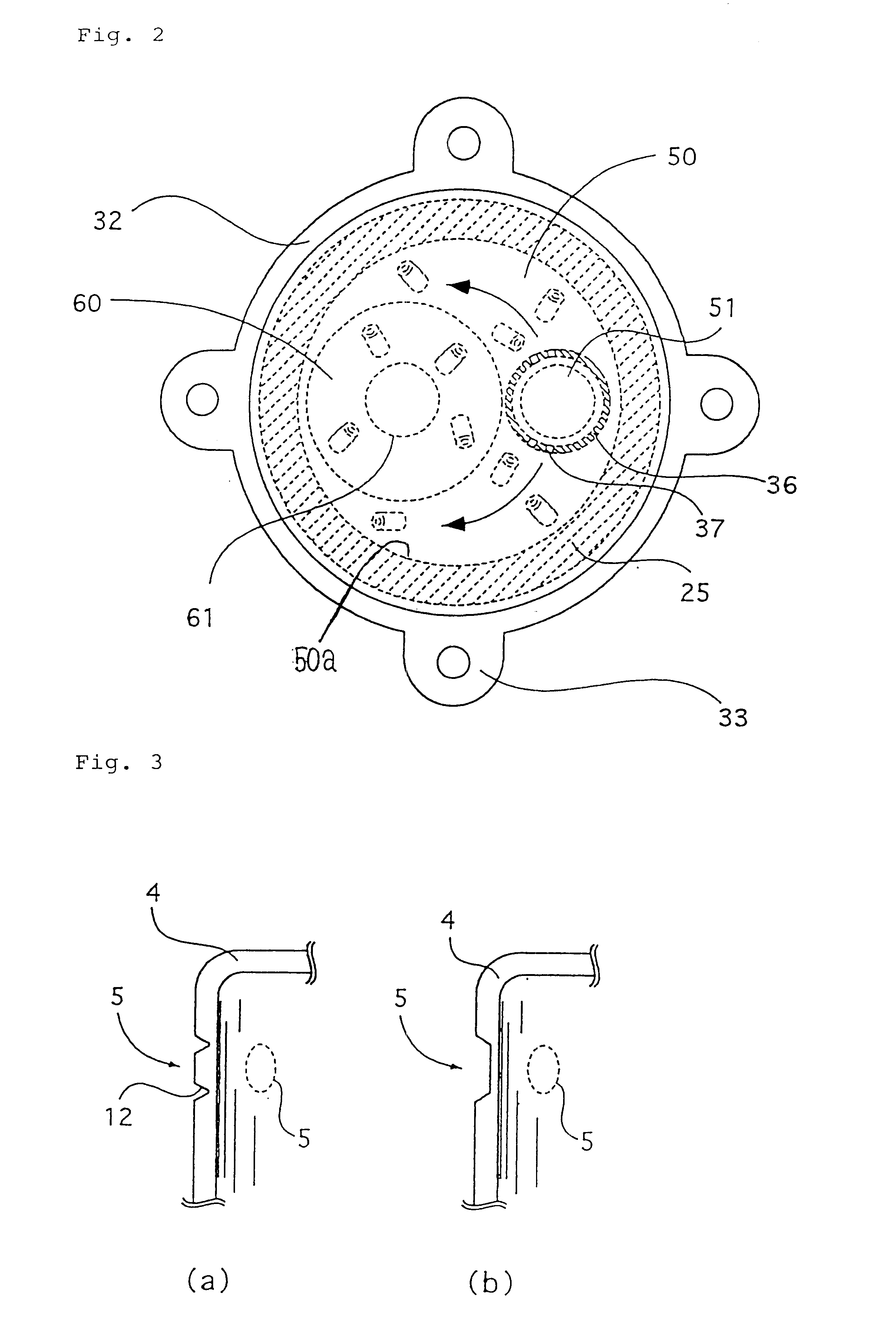
In the gas generator shown in this figure, a first combustion chamber 1105a and a second combustion chamber 1105b are defined by an inner cylindrical member 1104, and are disposed adjacent to each other concentrically in a housing 803. The inner cylindrical member 1104 is provided at its inner peripheral surface with a step notch 1106 at a predetermined height. A partition wall 1107 for defining the second combustion chamber 1105b and an ignition means accommodating chamber 1108 is disposed in the step notch 1106. In the present embodiment, as shown in an exploded perspective view in FIG. 29, the partition wall 1107 comprises a sectioning circular member 1150 which engages the step notch 1106 of the inner cylindrical member 1104 and a seal cup member ...


PUM

PropertyMeasurementUnit
Lengthaaaaaaaaaa
Pressureaaaaaaaaaa
Heightaaaaaaaaaa

Abstract

A gas generator for an air bag includes: a housing having top and bottom plates and a cylindrical wall provided between those plates; a cylindrical filter unit, provided inside the housing, at least one end of the filter unit having an inclining end surface such that the length of the filter unit in an axial direction thereof decreases as the distance from a central axis of the filter in a radial direction increases, an outer peripheral surface of the filter unit and an inner surface of the cylindrical wall defining a plenum; and a supporting portion formed inside the housing and having an inclining surface substantially parallel to the inclining end surface of the filter unit. The supporting portion engages with the inclining end surface such that the plenum is maintained even when the filter unit is urged to expand in the radial direction by the combustion gas.

Description

The present invention relates to a multistage gas generator for an air bag and an air bag apparatus using the gas generator.PRIOR ARTAn air bag system which is mounted on various kinds of vehicles and the like including automobiles, aims to hold an occupant by means of an air bag (a bag body) rapidly inflated by a gas when the vehicle collides at a high speed so as to prevent the occupant from crashing into a hard portion inside the vehicle such as a steering wheel, a windscreen due to an inertia and being injured. This kind of air bag system generally comprises a gas generator to be actuated according to a collision of the vehicle and discharge a gas, and an air bag to introduce the gas to inflate.It is desired that the air bag system of this type can safely restrain the occupant even when frame of the occupant (for example, whether a sitting height is long or short, whether an adult or a child, and the like), a sitting attitude (for example, an attitude of holding on the steering ...

Claims


Application Information

Patent Timeline
IPC IPC(8): B01D46/24B60R21/26B60R21/01B60R21/272B01J7/00B60R21/217B60R21/263B60R21/264E02F3/26E02F9/20G01S5/14
CPCB01D46/24B01D46/2403B01D46/4218B60R21/2644B01D2279/10B60R2021/01006B60R2021/26029B60R2021/26064B60R2021/2633B60R2021/2648B60R21/272B60R21/26B60R21/264B60R21/217
Inventor NAKASHIMA, YOSHIHIROOHJI, NOBUYUKIKATSUDA, NOBUYUKI
Owner DAICEL CHEM IND LTD
Why Eureka
Try Eureka