System and method for processing squint mapped synthetic aperture radar data

a synthetic aperture radar and radar signal technology, applied in the field of radar, can solve the problems of degraded impulse response, large memory required to store intermediate two-dimensional data, and limited scope of the squint angle sar system,

Inactive Publication Date: 2002-12-10
RAYTHEON CO
View PDF8 Cites 44 Cited by
  • Summary
  • Abstract
  • Description
  • Claims
  • Application Information

AI Technical Summary

Problems solved by technology

A SAR system is limited to a relatively small antenna with a wide beam because it must fit on an aircraft or satellite.
Processing SAR data collected with a squint angle has been a challenging task due to the constantly changing distance between the radar and a ground target.
Two decades ago, the main problems associated with processing this data were the cost of large memory required to store the intermediate two-dimensional data and the degraded impulse response due to lack of processing algorithms designed for squint mapping.
Unfortunately, there are many disadvantages associated with these prior approaches.
For example, the disadvantages associated with polar format algorithm in squint mode processing include (1) a discontinuity of pixel amplitude and phase among image subpatches and (2) considerable complexity associated with the subpatch approach.
This makes it very difficult to efficiently integrate other processes including autofocus, impulse response weighting, and radiometric compensation into the processing chain.
In short, these algorithms have been difficult to optimize with respect to the efficiency of the entire processing chain including autofocus processing, impulse response weighting, coordinate rotation, and radiometric compensation.
In addition, due to the complexity of these algorithms, the cost associated with software development and maintenance has been relatively high.
Therefore, a unique azimuth reference function will not be able to focus all targets in the same range bin.
For some SAR systems where the focusing parameter difference in one range bin is significant such that a single range migration curve cannot approximate all targets, slight degradation would occur on the final impulse response.

Method used


Image

  • System and method for processing squint mapped synthetic aperture radar data
  • System and method for processing squint mapped synthetic aperture radar data
  • System and method for processing squint mapped synthetic aperture radar data

Examples


Embodiment Construction

Illustrative embodiments and exemplary applications will now be described with reference to the accompanying drawings to disclose the advantageous teachings of the present invention.

While the present invention is described herein with reference to illustrative embodiments for particular applications, it should be understood that the invention is not limited thereto. Those having ordinary skill in the art and access to the teachings provided herein will recognize additional modifications, applications, and embodiments within the scope thereof and additional fields in which the present invention would be of significant utility.

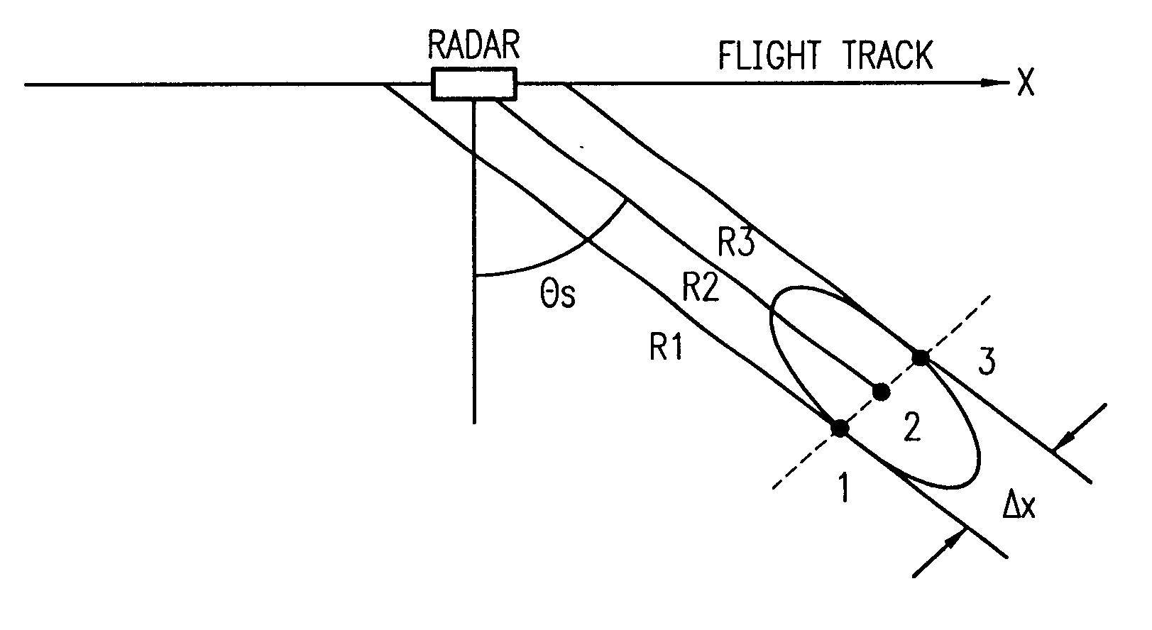
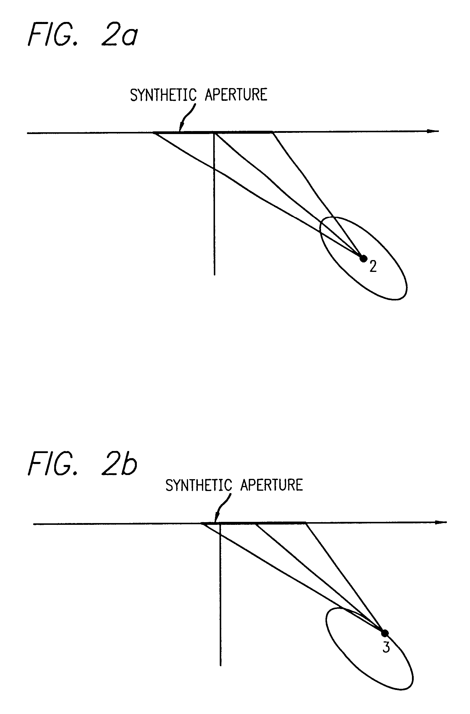
The original range-Doppler algorithm was formulated in the coordinates including range, slow time, and Doppler. In accordance with the extended range-Doppler processing method of the present invention, coordinates are formulated including range (r), along-track coordinate (x), azimuth coordinate (x'), and their corresponding frequency space k.sub.r, k.sub.x, and...


PUM


Abstract

A method for processing squint-mapped synthetic aperture radar data of the present invention. The inventive method includes the steps of effecting range compression of the data; deskewing the data; performing a Fourier transform with respect to the deskewed data; providing a range migration interpolation of the transformed data; effecting a frequency remapping of the range interpolated data; and performing an inverse Fourier transform with respect to the deskewed data.

Description

1. Field of the InventionThe present invention relates to radar. More specifically, the present invention relates to systems and methods for synthetic aperture radar signals.2. Description of the Related ArtRadar systems are used for a variety of applications. For certain applications, certain types of radar are preferred. For example, for numerous aircraft and satellite applications, synthetic aperture radar (SAR) is frequently used. A synthetic aperture radar images targets on the ground from the air. (See "Radar" Microsoft.RTM. Encarta.RTM. Encyclopedia 2000) A SAR system uses the movement of an airplane or satellite carrying it to make the antenna seem much larger than it is. The ability of radar to distinguish between two closely spaced objects depends on the width of the beam that the antenna sends out. The narrower the beam, the better its resolution. A narrow beam requires a large antenna. A SAR system is limited to a relatively small antenna with a wide beam because it must...

Claims


Application Information

Patent Timeline
Patent Type & Authority Patents(United States)
IPC IPC(8): G01S13/00G01S13/90
CPCG01S13/9035G01S13/9011G01S2013/9041G01S13/904G01S13/9041
Inventor JIN, MICHAEL Y.LAWRENCE, MICHAEL E.
Owner RAYTHEON CO
Why Eureka
Try Eureka