
Scanning radar angular super-resolution imaging method based on maximum posterior

A scanning radar and angle super-resolution technology, which is applied in the field of radar imaging technology and signal processing, can solve the problems of easy false targets and noise sensitivity, and achieve the effect of suppressing noise and improving estimation accuracy

Active Publication Date: 2017-10-20
UNIV OF ELECTRONICS SCI & TECH OF CHINA
View PDF11 Cites 18 Cited by
  • Summary
  • Abstract
  • Description
  • Claims
  • Application Information

AI Technical Summary

Problems solved by technology

Literature "Y.Zha, Y.Huang, J.Yang, J.Wu, Y.Zhang and H.Yang," An improved Richardson-Lucy algorithm for radar angular super-resolution," 2014IEEE Radar Conference, Cincinnati, OH, 2014 ,pp.0406-0410." Based on the traditional Richardson-Lucy (R-L) method, Laplace prior is added to improve the azimuth resolution, but it is sensitive to noise and prone to false targets

Method used


Image

  • Scanning radar angular super-resolution imaging method based on maximum posterior
  • Scanning radar angular super-resolution imaging method based on maximum posterior
  • Scanning radar angular super-resolution imaging method based on maximum posterior

Examples


Embodiment Construction

[0054] In order to facilitate those skilled in the art to understand the technical content of the present invention, the present invention will be further described below in conjunction with the accompanying drawings.

[0055] The present invention mainly uses simulation experiments to demonstrate the feasibility and effectiveness of the proposed radar angle super-resolution method. All steps and conclusions in the present invention are verified to be correct on the Matlab2015 simulation platform, and the present invention will be further elaborated below in conjunction with the accompanying drawings and specific implementation steps.

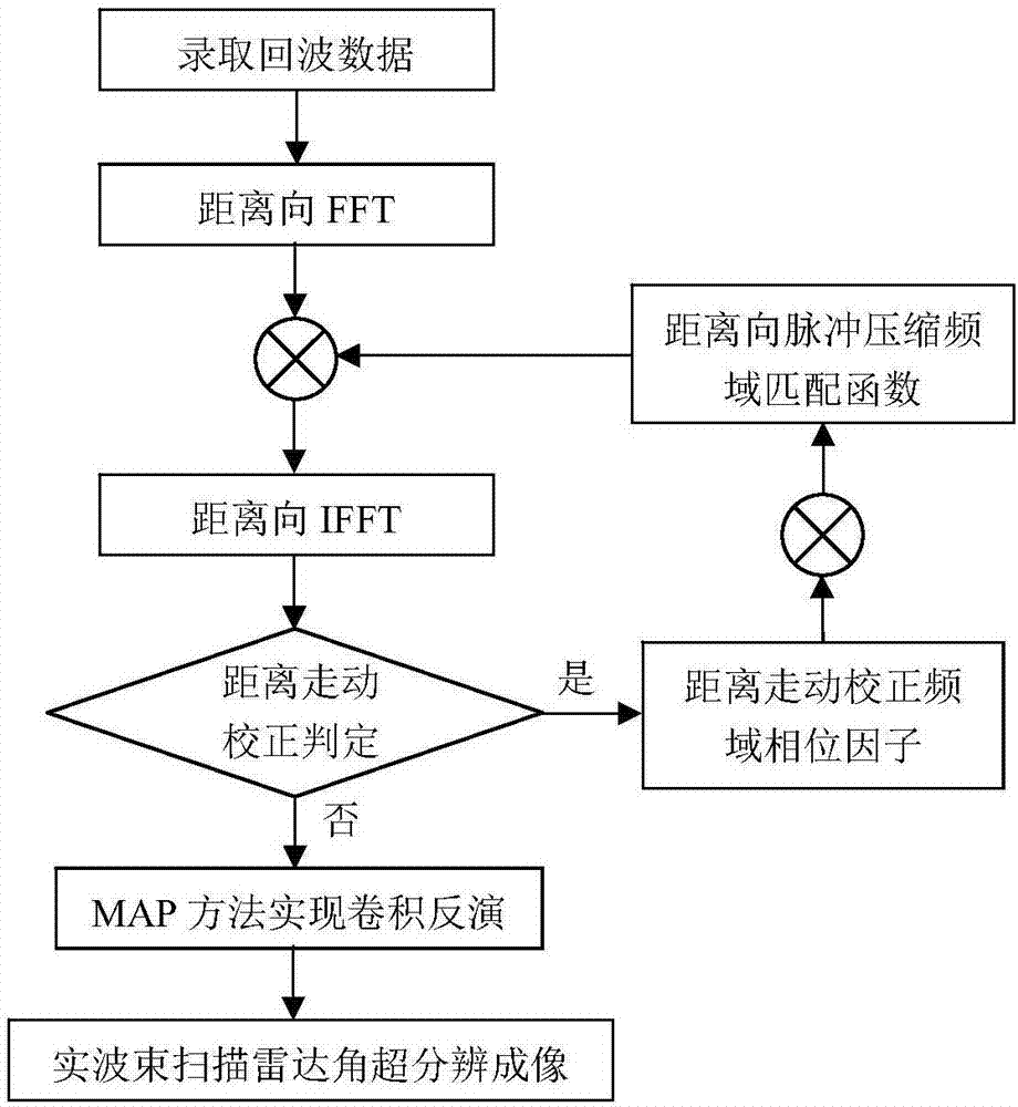
[0056] Such as figure 1 Shown is the solution flow chart of the present invention, the technical solution of the present invention is: a scanning radar angle super-resolution imaging method based on maximum a posteriori, comprising:

[0057] S1. The chirp signal is transmitted through the real beam scanning radar to obtain the two-dimensional ...


PUM


Abstract

The invention discloses a scanning radar angular super-resolution imaging method based on maximum posterior, which is applied to the fields of radar imaging technology and signal processing. The method includes the following steps: a linear frequency modulation signal is emitted by a real beam scanning radar, a two-dimensional echo signal of an irradiated region is acquired, and range high-resolution is implemented through a pulse compression technology and a range migration correction technology; the azimuth echo of the scanning radar is modeled as a convolution form of a radar antenna pattern and a target scattering coefficient according to an azimuth echo model of the scanning radar; and on the basis, radar angular super-resolution imaging is implemented using a convolution inversion method based on Maximum A Posteriori (MAP).

Description

technical field [0001] The invention belongs to the field of radar imaging technology and signal processing, in particular to super-resolution imaging of real beam scanning radar azimuth angle. Background technique [0002] Radar imaging technology, as an active aviation and aerospace remote sensing method, has the characteristics of all-day and all-weather work, and has been widely used in military and civilian fields. The high-resolution imaging technology of radar has always been the key point and difficulty of technical research. For the high-resolution imaging of the radar platform's forward-looking area, it has shown great application value in sea detection and imaging, environmental monitoring, and disaster rescue. However, limited by its imaging mechanism, synthetic aperture radar and Doppler beam sharpening technology cannot achieve high-resolution imaging of the radar front-sight area. At present, real-beam radar imaging mostly uses airborne scanning radar, which...

Claims


Application Information

Patent Timeline
IPC IPC(8): G01S13/89G01S7/41
CPCG01S7/41G01S13/89
Inventor 张寅李昌林吴阳毛德庆徐帆云黄钰林杨建宇
Owner UNIV OF ELECTRONICS SCI & TECH OF CHINA
Learn More