
Geophysical inertial navigation system

a technology of geophysical inertial navigation and navigation system, applied in the direction of navigation instruments, instruments, surveying and navigation, etc., can solve the problems of inability to continue safe flights under meteorological conditions (imc) with only gps capability, use expensive optical fiber gyros, and existing ins are too costly for typical g/a installations

Inactive Publication Date: 2002-12-10
BURNS ALAN ALEXANDER
View PDF7 Cites 90 Cited by
  • Summary
  • Abstract
  • Description
  • Claims
  • Application Information

AI Technical Summary

Problems solved by technology

However, this transition leads to the need for a reliable, autonomous, and inexpensive backup system should the GPS signals or airborne GPS receiving equipment be lost or compromised.
Continuation of safe flights under Instrument Meteorological Conditions (IMC) with only GPS capability would be impossible.
Modern INS generally use expensive optical fiber gyros.
However, existing INS are too costly for typical G / A installations, particularly those involving light, piston-powered aircraft.
There is no guarantee that any particular ground-based dedicated or chance radiator or group of radiators will be available in an emergency.
Under IMC, there is also no guarantee that usable surface features will be visible and identifiable, even with advanced terrain and feature recognition devices.

Method used


Image

  • Geophysical inertial navigation system
  • Geophysical inertial navigation system
  • Geophysical inertial navigation system

Examples


Embodiment Construction

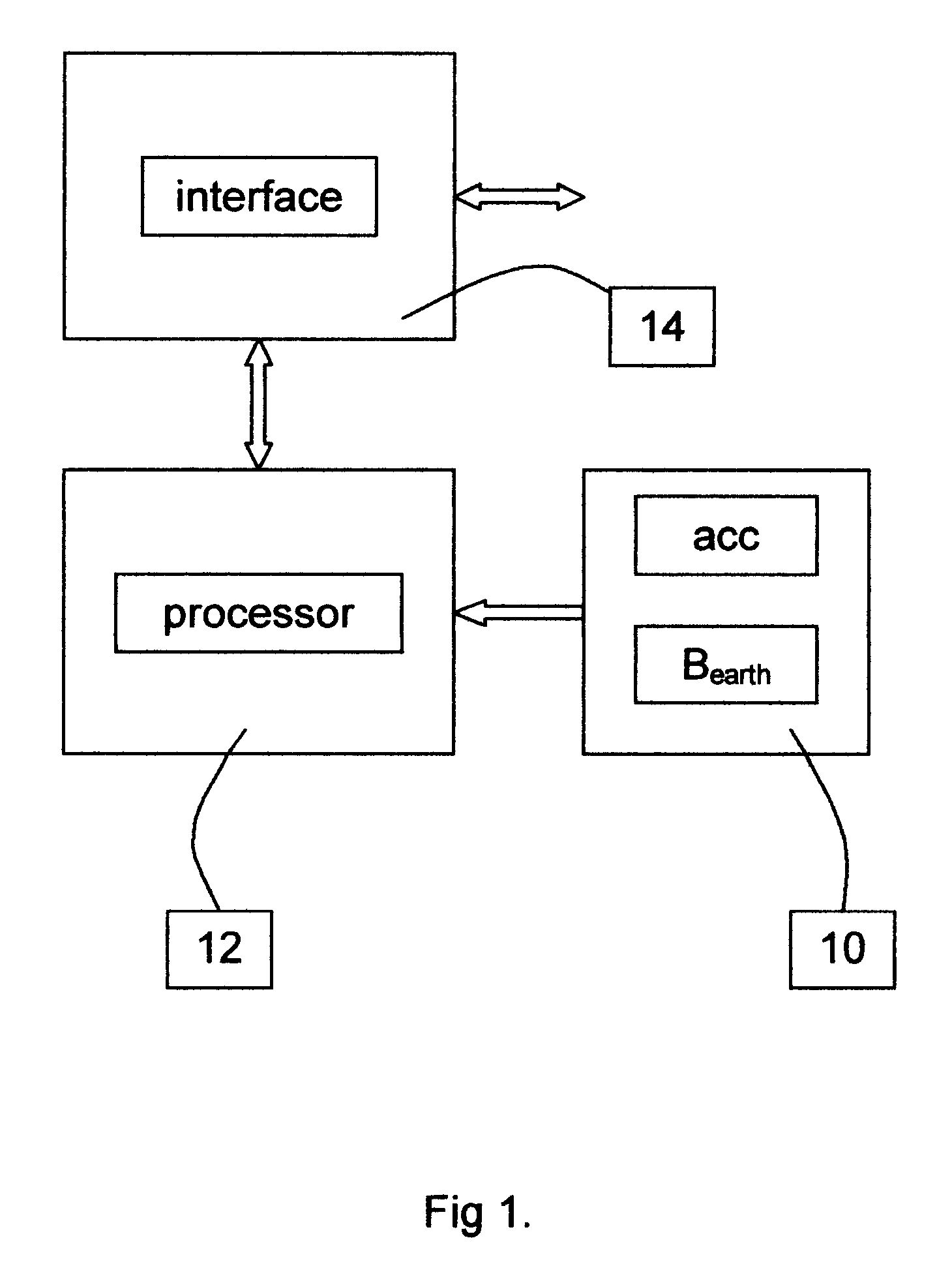
FIG. 1 is a block diagram showing the primary elements of a geophysical inertial navigation system. The primary elements are a processor unit 10, an acceleration- and geomagnetic-field sensor unit 12, and an interface unit 14. In the preferred embodiment, the geophysical quantities sensed are the direction and strength of the geomagnetic field and the direction and strength of the earth's gravity. Sensor unit 12 is strapped down to the body (not shown) of the vehicle (aircraft), and may or may not be, integrated into the same package as the processor unit 10 and interface unit 14. In some applications, it would be advantageous to mount sensor unit 12 remotely from the processor and interface units 10 and 14. The components of sensor unit 12 may be separated as well. For example, mounting the sensor unit 12 in the tail of an aircraft or at a wingtip would reduce any interfering effects of magnetic fields form on-board objects and electrical currents. In addition, processor unit 10 an...


PUM


Abstract

An inertial navigation system employs geophysical (earth's magnetic and gravity) field sensors to measure body rotations of an aircraft or other vehicle. In effect, these replace expensive laser ring gyros used in conventional inertial navigation systems. The vector components of the geomagnetic field may be incorporated directly into the state vector describing the vehicle's attitude, acceleration, velocity, and position. A predictive filter (e.g. Kalman) operates on measured and predicted geophysical field components and on-board accelerometers. Predicted geophysical field components are obtained from maps and / or models of the earth's magnetic and gravity fields.

Description

BACKGROUND--FIELD OF INVENTIONThis invention relates to inertial or dead reckoning navigation, in particular to that of aircraft.BACKGROUND--DESCRIPTION OF PRIOR ARTThere is a need for a low-cost navigation system to act effectively and inexpensively as a backup in the vent of failure to receive and process reliable Global Positioning System (GPS) navigation signals. This is particularly important for single-engine General Aviation (GIA) applications, where cost is often the overriding consideration. The United States Government is planning to phase out existing ground-based navigation systems--the VOR (VHF Omni-Directional Range) and typically associated DME (Distance Measuring Equipment) network, the ILS (Instrument Landing System), and non-directional beacons (NDE). Replacing these legacy systems with GPS will realize considerable cost savings. However, this transition leads to the need for a reliable, autonomous, and inexpensive backup system should the GPS signals or airborne G...

Claims


Application Information

Patent Timeline
IPC IPC(8): G01C21/10G01C17/30G01C17/00G01C21/16
CPCG01C17/30G01C21/165G01C21/1654
Inventor BURNS, ALAN ALEXANDER
Owner BURNS ALAN ALEXANDER
Features
  • Generate Ideas
  • Intellectual Property
  • Life Sciences
  • Materials
  • Tech Scout
  • Unparalleled Data Quality
  • Higher Quality Content
  • 60% Fewer Hallucinations
Learn More