System and method for three-dimensional ultrasound imaging using a steerable probe

a three-dimensional ultrasound and steerable technology, applied in tomography, using reradiation, instruments, etc., can solve the problems of difficult to move the probe 108 with a constant velocity, inability to accurately calculate the distance, and inability to recognize the overall structure or shape of the targ

Inactive Publication Date: 2002-12-17
MEDISON CO LTD
View PDF9 Cites 40 Cited by
  • Summary
  • Abstract
  • Description
  • Claims
  • Application Information

AI Technical Summary

Problems solved by technology

Thus, the overall structure or shape of the target is not readily recognized.
When the user moves the probe 108 manually, however, it is difficult to move the probe 108 with a constant velocity.
Without knowing the velocity of the probe 108, it is not possible to accurately calculate the distance even if when 2-D images were generated is known.
The speckle noise means a noise appearing on a screen as a speckle, which is caused when objects in the scanning area smaller than the wavelength of an ultrasound signal disperses or interferes with the reflected signal.
However, when the target has substantially different characteristics from the experimental phantom, which is to be scanned, the estimated distance between two 2-D image frames of the target would have errors.
Also, it is difficult to extract the speckle regions from the respective 2-D image frames.
Furthermore, it is time-consuming to extract the speckle regions from the respective 2-D image frames.

Method used


Image

  • System and method for three-dimensional ultrasound imaging using a steerable probe
  • System and method for three-dimensional ultrasound imaging using a steerable probe
  • System and method for three-dimensional ultrasound imaging using a steerable probe

Examples


Embodiment Construction

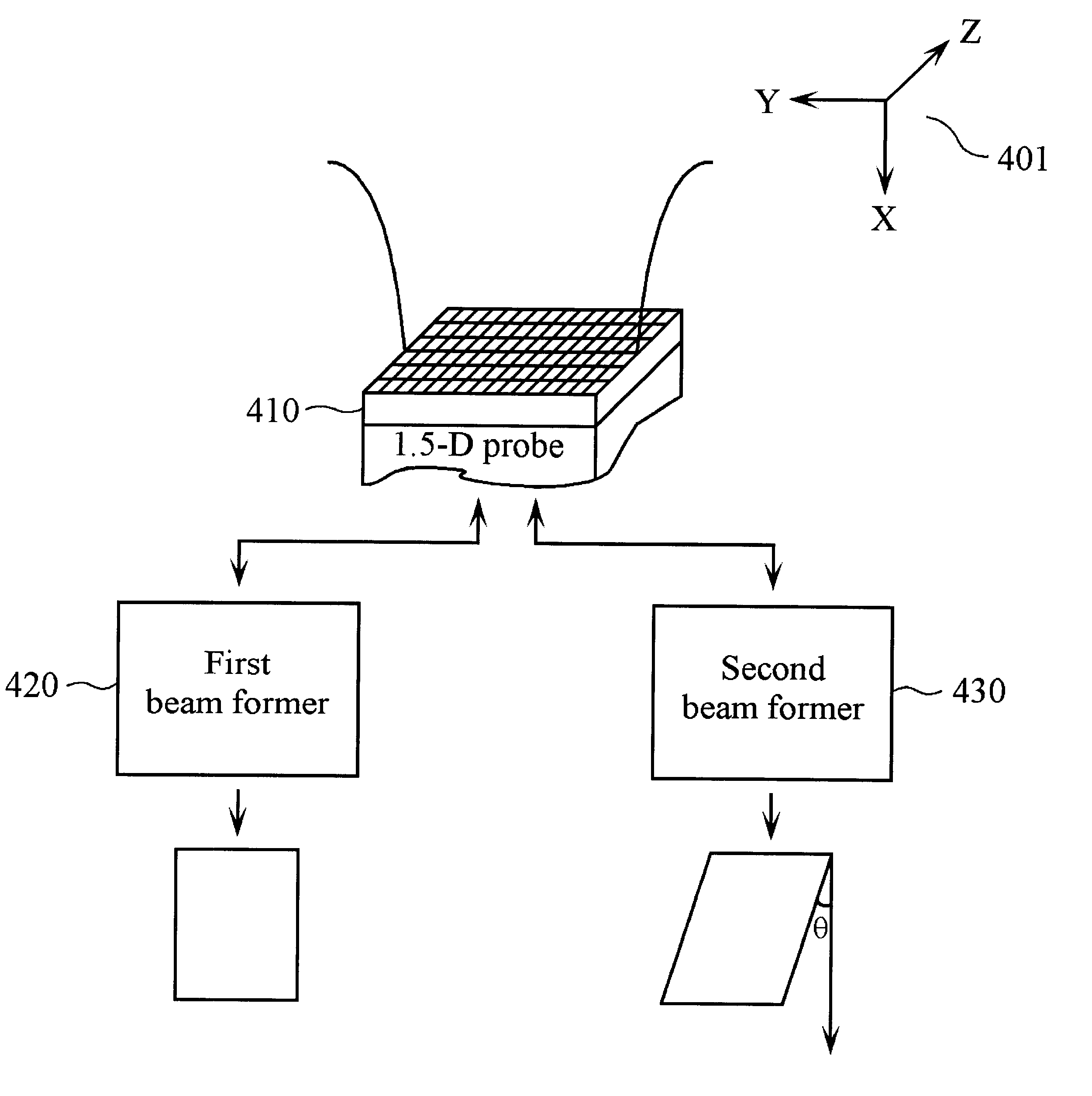
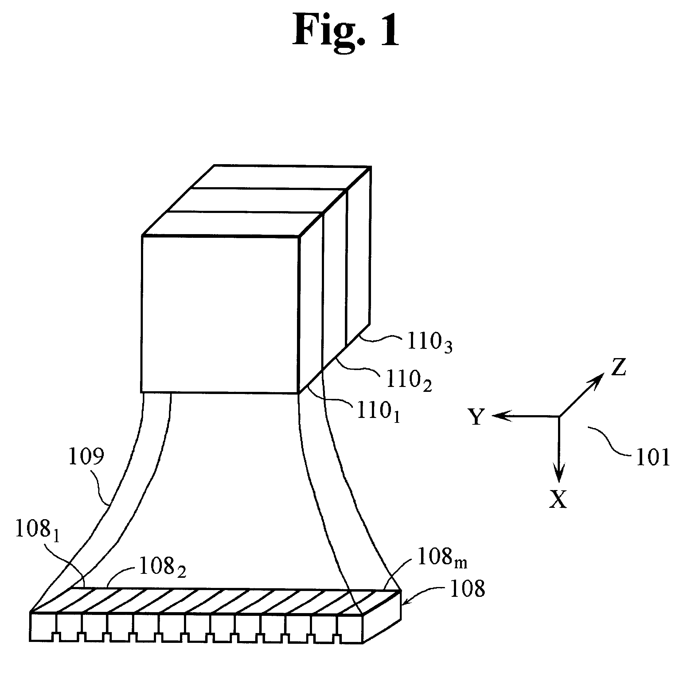
FIG. 4 shows a diagram for explaining a procedure of generating a pair of image frames of a target (not shown) to be examined by using a 1.5-D probe 410. In accordance with an embodiment of the present invention, the 1.5-D probe 410 is used to generate a pair of image frames of the target, the two image frames being at an angle with respect to each other. As shown in FIG. 4, the frame of reference is an orthogonal depth-lateral-elevation (X-Y-Z) coordinate system 401 similar to the reference numeral 101 in FIG. 1. X-axis represents the scanning depth; Y-axis represents the direction of arrangement of transducers; and Z-axis represents the moving direction of the 1.5-D probe 410. It is noted that a 1-D probe consists of a plurality of in-line transducers while the 1.5-D probe 410 is made of a multiplicity of such 1-D probes. The 1-D probe arrayed on the lateral direction can focus ultrasound signals on one scan plane, e.g., X-Y plane, only.

The 1.5-D probe 410 could focus ultrasound s...


PUM

PropertyMeasurementUnit
distanceaaaaaaaaaa
distanceaaaaaaaaaa
angleaaaaaaaaaa

Abstract

A system and a method generate a 3-D image by fast computing the distance between adjacent 2-D images. The method comprises the steps of: producing a first main frame, a second main frame parallel to the first main frame, and a supplementary frame inclined at an angle with respect to the first main frame; creating a virtual frame by using the first main frame and the supplementary frame; calculating a first correlation coefficient between the first main frame and the virtual frame; computing a second correlation coefficient between the first and second main frames; and estimating a distance between the first and second main frames. The system comprises a probe for generating pairs of image frames; a distance calculating unit for calculating distances between main frames of the pairs; and a screen for displaying a 3-D image of the target produced by using the distances.

Description

1. Field of the InventionThe present invention relates to a system and a method for generating a three-dimensional (3-D) image of an object by using two-dimensional (2-D) images of the object; and, more particularly, to a system and a method for generating a 3-D image by fast computing the distance between adjacent 2-D images.2. Description of the Related ArtUltrasound imaging systems are gaining popularity in medical diagnostics and non-destructive inspection fields. In ultrasound imaging systems, an array of transducers or a probe generate and transmit an ultrasound signal and receive the ultrasound signal reflected from a target being scanned. The received ultrasound signal is processed to display an image of the target.Two-dimensional (2-D) ultrasound imaging systems generate a 2-D image of a target by transmitting and receiving an ultrasound signal in a single scan plane. The generated 2-D image represents only one cross-section of the target. Thus, the overall structure or sha...

Claims


Application Information

Patent Timeline
Patent Type & Authority Patents(United States)
IPC IPC(8): G01S15/89G01S15/00G01B17/00A61B8/00G01B17/06G01N29/44G01S7/52G03B35/00G06T1/00G06T7/60H04N7/18H04N13/04
CPCG01S15/8993Y10S128/916A61B8/13
Inventor KIM, SANG-HYUNKO, SEOK-BIN
Owner MEDISON CO LTD
Why Eureka
Try Eureka