Plasma display panel with various electrode projection configurations

a technology of projection configuration and display panel, which is applied in the direction of electrodes, discharge tubes, luminescnet screens, etc., can solve the problems of screen use and brightness disadvantage, and achieve the effect of less burden

Inactive Publication Date: 2002-12-17
HITACHI PLASMA PATENT LICENSING
View PDF14 Cites 36 Cited by
  • Summary
  • Abstract
  • Description
  • Claims
  • Application Information

AI Technical Summary

Benefits of technology

In the present invention, the plan-view shape of the main electrodes disposed equidistantly is the shape of linear belts of constant width having partial cut-offs in such a manner that all cells have an equal electrode area. Since an electric field is not generated at a cut-off portion, the discharge produced on one side of the main electrode can be prevented from expanding to the other side thereof. Because the area of the electrode decreases by the area of the cutoff, discharge current decreases, so that a drive circuit is less burdened. Decline in brightness with the decrease of the discharge current can be compensated by raising the frequency of drive voltage for sustaining light emission.

Problems solved by technology

With this typical configuration, since the reverse gap does not contribute to light emission, the use of the screen is limited and is disadvantageous in brightness.

Method used


Image

  • Plasma display panel with various electrode projection configurations
  • Plasma display panel with various electrode projection configurations
  • Plasma display panel with various electrode projection configurations

Examples


first embodiment

FIG. 3 is a plan view illustrating an exemplary configuration of the main electrodes in accordance with the present invention.

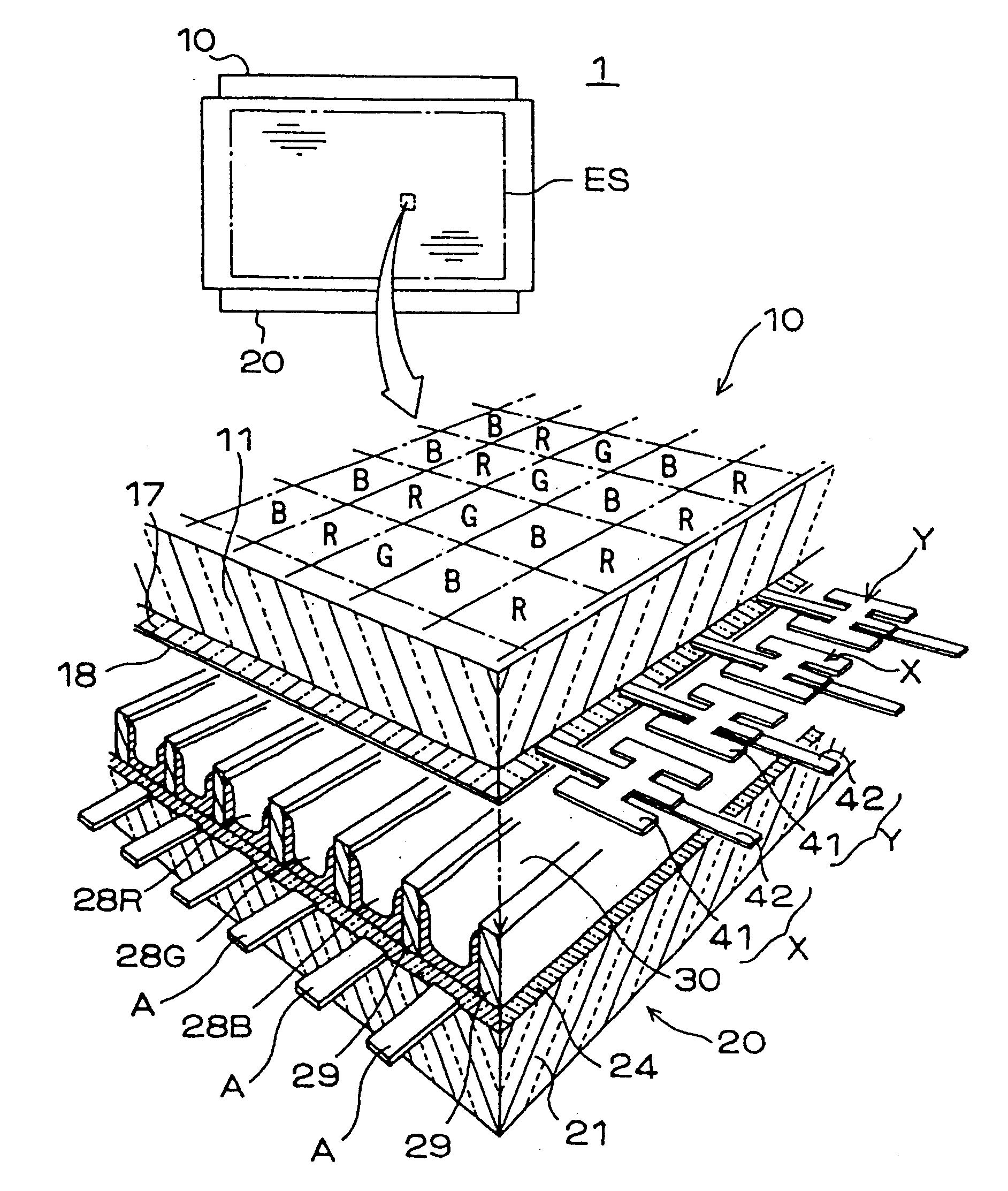
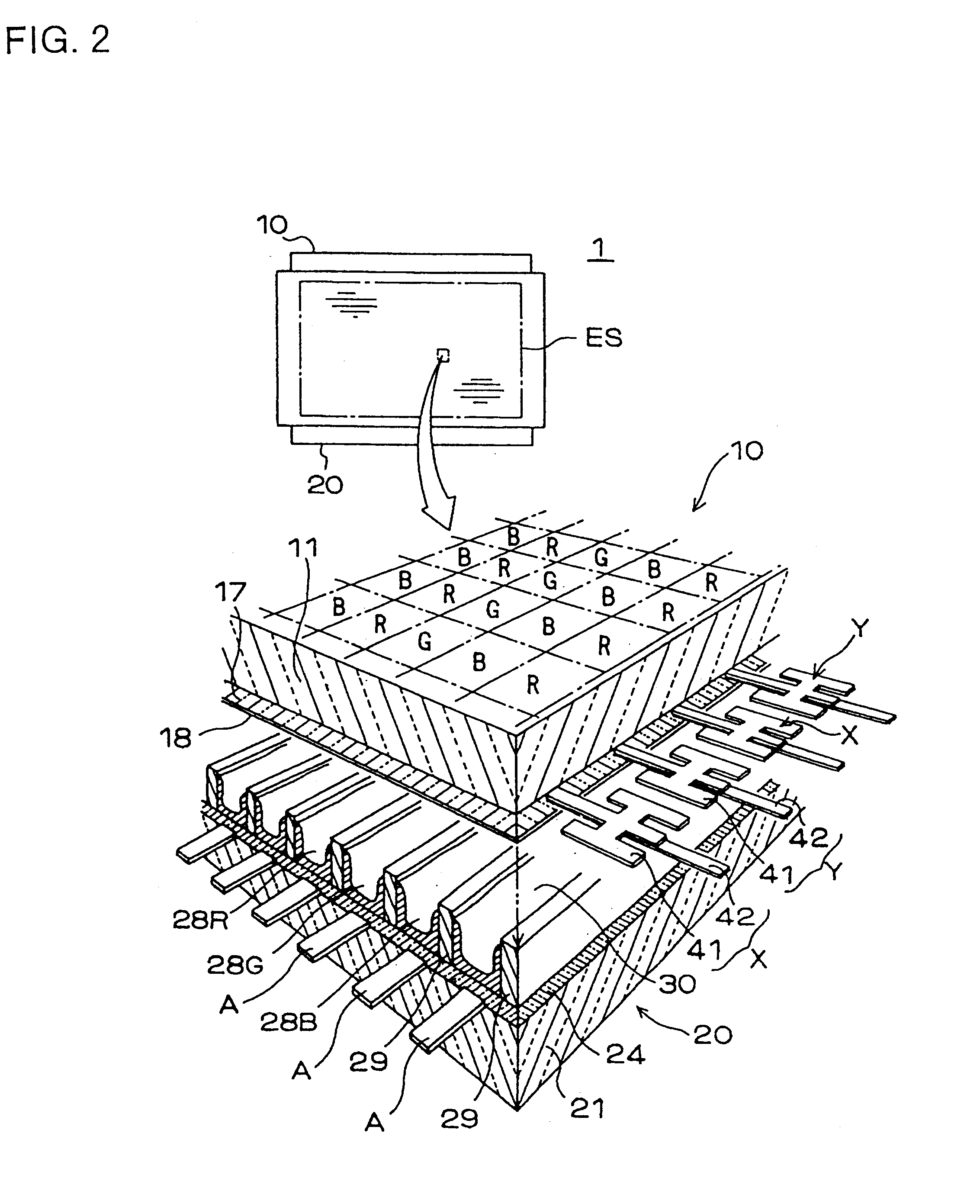
The main electrodes X an Y are each composed of an electrically conductive transparent film 41 and a metal film 42 as described above. Since the entire metal film 42 is overlaid on the conductive transparent film 41 within the range of the screen, the plan-view shape of the conductive transparent film 41 itself is the shape of the main electrode X or Y.

The conductive transparent film 41 is patterned to include a belt-shaped base 411 linearly extending along the full length of the screen in the row direction and T-shaped protrusions 412 extending from the base 411 toward an adjacent conductive transparent film 41. In each of the columns partitioned by the barrier ribs, the protrusions 412 project on both sides of the base 411. The distance between the end of the protrusion 412 on one side and the end of the protrusion 412 on the other side is the width w2 of t...

second embodiment

FIG. 11 is a plan view illustrating a configuration of main electrodes in accordance with the present invention.

Also in a PDP 2 shown in FIG. 11, main electrodes Xf and Yf are each composed of a conductive transparent film 41f and a metal film 42f. The conductive transparent film 41f is in the shape of a linear belt of constant width which has openings. This shape corresponds to that of FIG. 3 wherein the end edges of the T-shaped protrusions 413 and 414 are continued in the row direction. This configuration is suitable for the case where the cell pitch in the row direction is too small to allow the T-shaped protrusions to have a sufficient width at the surface-discharge gap.

third embodiment

FIG. 12 is a plan view illustrating a configuration of main electrodes in accordance with the present invention.

In a PDP 3 shown in FIG. 12, main electrodes Xg and Yg are each composed of two belt-shaped portions 431 and 432 which spacedly extend along the full length of the screen ES in the row direction and a connect portion 425 for electrically connecting the belt-shaped portions 431 and 432 outside the screen ES. The belt-shaped portions 431 and 432 are laminates of a belt-shaped conductive transparent film and a belt-shaped metal film having a smaller width than the conductive transparent film. The metal film is overlaid on the conductive transparent film, brought nearer to a side of the conductive transparent film distal to the surface-discharge gap. Only the metal films of the belt-shaped portions 431 and 432 are lead outside the screen ES and integrated with a metal film forming the connect portion 425. In the example shown in the figure, the belt-shaped portions 431 and 432...


PUM


Abstract

A plasma display panel includes a plurality of row electrodes defining rows of a screen. The row electrodes are arranged at intervals so that adjacent row electrodes are capable of serving as an electrode pair for generating a surface discharge. Each of the row electrodes includes a belt-shaped base extending along the full length of the screen in a direction of the rows and protrusions extending from the base toward an adjacent row electrode in every column.

Description

CROSS-REFERENCE TO RELATED APPLICATIONThis application is related to Japanese application No. HEI 10(1998)-287424 filed on Oct. 9, 1998, whose priority is claimed under 35 USC .sctn.119, the disclosure of which is incorporated by reference in its entirety.BACKGROUND OF THE INVENTION1. Field of the InventionThe present invention relates to a plasma display panel (PDP) of a surface-discharge type and a display device using the same.PDPs have become widely used for television monitors, video monitors for computers and the like since color display became practical with PDPs. For further spread of the PDPs, structures suitable for high definition are being developed.2. Description of Related ArtThree-electrode AC surface-discharge PDPs are commercialized as color display devices. Here, the surface-discharge structure means a structure in which a first main electrode and a second main electrode are arranged in parallel on an inner surface of one of paired substrates (referred to as a firs...

Claims


Application Information

Patent Timeline
Patent Type & Authority Patents(United States)
IPC IPC(8): G09G3/28H01J17/49G09G3/20G09G3/288G09G3/291G09G3/296G09G3/298H01J11/12H01J11/14H01J11/22H01J11/24H01J11/26H01J11/32H01J11/34H01J17/04
CPCG09G3/299H01J11/12H01J11/24G09G2330/021H01J2211/245H01J11/22
Inventor KUROGI, SEIKIUKAI, YOSHITAKAYOSHIDA, KENJIKATAYAMA, TAKASHINAKAHARA, HIROYUKI
Owner HITACHI PLASMA PATENT LICENSING
Why Eureka
Try Eureka