

Shared I/O ports for multi-core designs
a multi-core integrated circuit and shared technology, applied in the field of input/output (i/o) ports, can solve the problems of reducing the number of external pins available for use in any particular package design, and reducing the number of external pins. designers have been forced to rely on expensive packaging solutions,
- Summary
- Abstract
- Description
- Claims
- Application Information
AI Technical Summary
Problems solved by technology
Method used
Image

Examples
Embodiment Construction
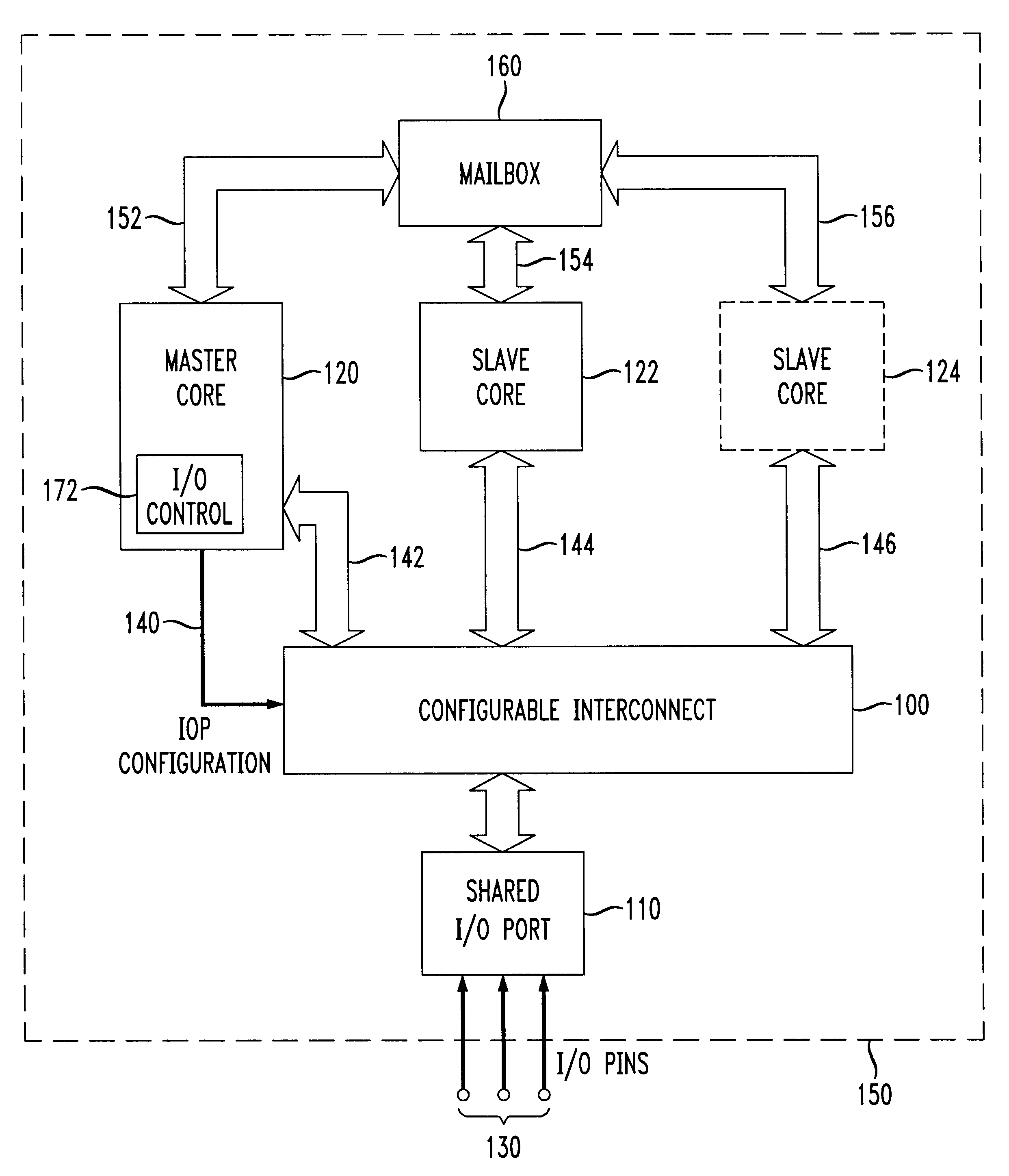
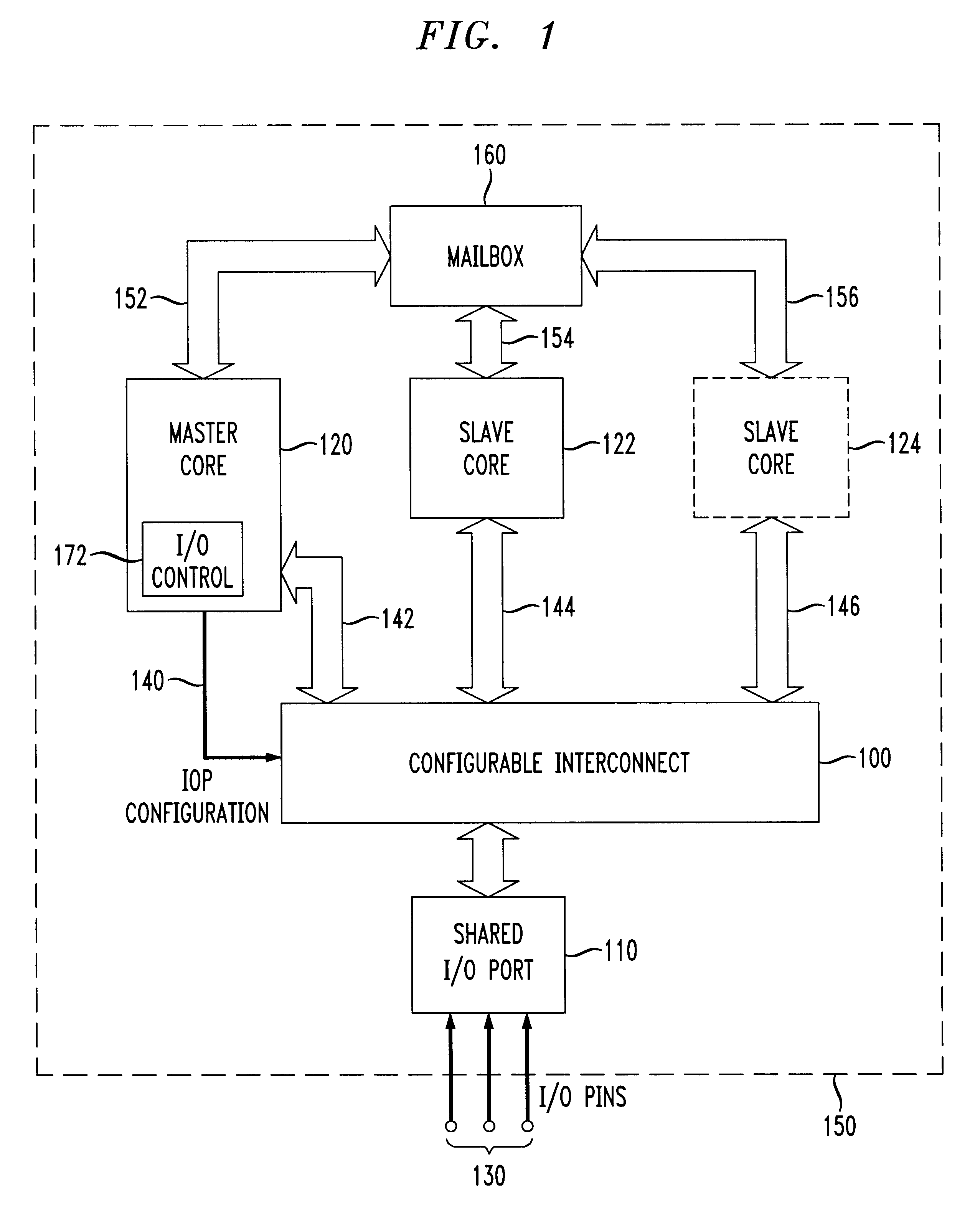
The present invention provides a shared I / O port and a configurable interconnect allowing any of a plurality of cores to access any pin of a shared I / O port. One core is designated as the master with respect to configuration of the shared I / O port(s). Non-master (i.e., slave) cores communicate with the master core, e.g., through the use of a "mailbox" location in a commonly accessible memory area, to request reconfiguration of a particular I / O port or I / O pin as desired.
With the ability to share general purpose I / O pins between two or more separate cores, designers are now armed with another design tool and technique for providing a cost-effective solution for interfacing each of the separate cores to the external world using a limited or rationed number of external pins. Depending upon the particular application, reconfigurable I / O pins in accordance with the principles of the present invention can be configured for use by any of the cores.
FIG. 1 shows an exemplary multiple-core de...
PUM
 Abstract
Description
Claims
Application Information