Eureka AIR delivers breakthrough ideas for toughest innovation challenges, trusted by R&D personnel around the world.

Method and apparatus for a non-oil-filled towed array with a novel hydrophone design and uniform buoyancy technique

a hydrophone and non-oil-filled technology, applied in the field of hydrophone systems and methods for sensing acoustic pressure waves, can solve the problems adversely affecting reliability, and prohibitively expensive and complex construction of non-oil-filled or solid towed arrays

Inactive Publication Date: 2002-12-24
INPUT OUTPUT INC
View PDF35 Cites 18 Cited by
  • Summary
  • Abstract
  • Description
  • Claims
  • Application Information

AI Technical Summary

Problems solved by technology

Current methods of constructing non-oil-filled or solid towed arrays have proven to be prohibitively expensive and complex due to their method of construction, which adversely affects reliability.
As a result, solid towed arrays, while demonstrating substantial advantages over oil filled arrays, have met with limited acceptance within the seismic and surveillance communities due to their high price and unreliability.
The primary cause of failure of solid towed arrays results from the requirement to make electrical connections for each of the numerous hydrophones that make up a single channel in an array.
The primary problem with this design is the fact that there is no bond between the polyethylene foam and both the inner and outer jackets since they are dissimilar materials.
Attempted solutions to this problem have proven to be unreliable.
Thus, there is a need for a method of constructing a solid or non-oil-filled hydrophone which does not enable formation of a path way for water to migrate up and down the length of the cable when the outer protective cable shield is damaged or a leak otherwise occurs and which provides a cost effective method and apparatus for a solid hydrophone.
The result of prior methods, however, has been a significant variation in the amount of buoyancy achieved.
Prior methods have been unable to precisely control the amount of buoyancy in areas of the cable where additional buoyancy is desired.

Method used


Image

  • Method and apparatus for a non-oil-filled towed array with a novel hydrophone design and uniform buoyancy technique
  • Method and apparatus for a non-oil-filled towed array with a novel hydrophone design and uniform buoyancy technique
  • Method and apparatus for a non-oil-filled towed array with a novel hydrophone design and uniform buoyancy technique

Examples


Embodiment Construction

An embodiment of a hydrophone provides a polymer film, air backed bender design, that unlike previous designs will not reduce the circumferential length of the polymer film with an increase in hydrostatic pressure. In certain embodiments, a method and apparatus provides a polymer hydrophone that exhibits minimal change in sensitivity with depth change and provides a substantially unlimited crash depth.

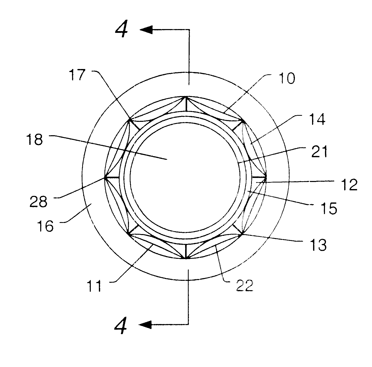
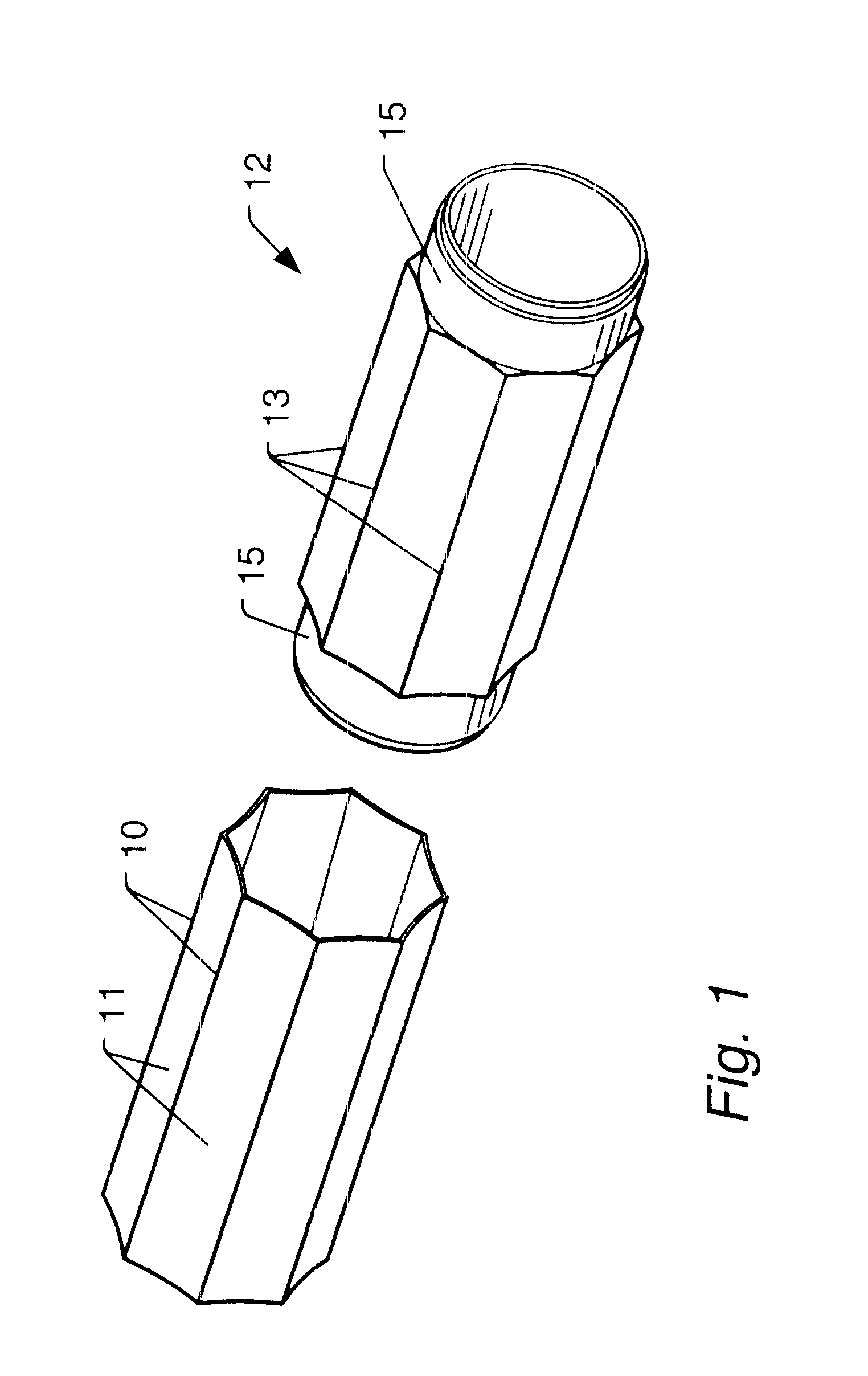
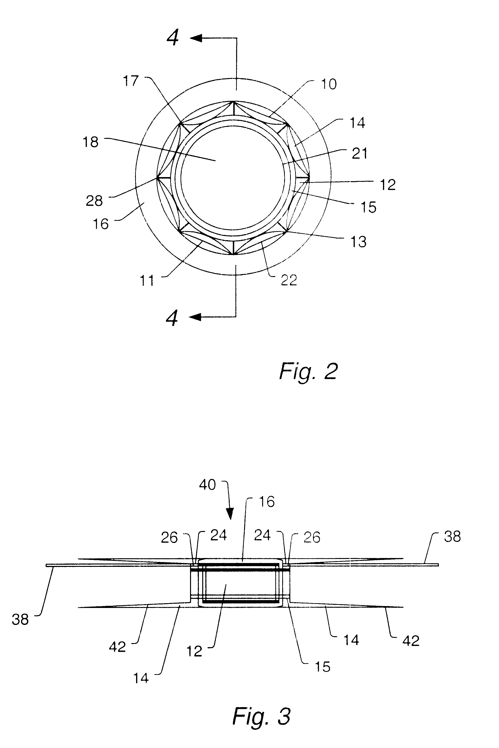
Turning now to FIG. 1, an embodiment of diaphragm 10 and back plane 12 are illustrated. Diaphragm 10 slides over back plane 12. Minimal sensitivity to depth change and substantially unlimited crush depth are provided by a design comprising the hydrophone diaphragm 10 having a series of concave faces 11 that run longitudinally along the length of the hydrophone diaphragm 10 and discretely around the circumference of the hydrophone diaphragm 12. In the example of FIG. 1, the eight concave surfaces of diaphragm 10 occupy the eight octants around the circumference of back plane 12. Each of...


PUM


Abstract

A structure and method for constructing a non-oil-filled towed array providing a single cable entry point for each channel irregardless of the number of hydrophones used to make up a hydrophone group or array is described. The method and apparatus enables uniform buoyancy of the hydrophone array and the primary cable around which the hydrophone array is wound. Uniform buoyancy is achieved through the addition of hollow micro-spheres into a Reaction Injection Molded (RIM) polyurethane material used to mold the hydrophones. Additional buoyancy may be desired adjacent heavier cable sections where connectors and telemetry modules are located. An embodiment enables precise adjustment of hydrophone cable buoyancy by providing precise adjustment of the concentration of hollow glass micro-spheres in areas where more or less buoyancy is desired.

Description

1. Field of the InventionThe present invention relates to a system and method for hydrophones for sensing acoustic pressure waves. In particular the invention relates to a technique for obtaining uniform buoyancy and increased sensitivity utilizing a hollow microsphere loaded reaction injection molding polyurethane material.2. Description of the Related ArtCurrent methods of constructing non-oil-filled or solid towed arrays have proven to be prohibitively expensive and complex due to their method of construction, which adversely affects reliability. Such techniques are described in U.S. Pat. Nos. 5,774,423; 5,361,240; 5,883,857; and 4,733,378. As a result, solid towed arrays, while demonstrating substantial advantages over oil filled arrays, have met with limited acceptance within the seismic and surveillance communities due to their high price and unreliability. Thus there is a need for a technology which addresses the primary causes of high cost and low reliability with a unique m...

Claims


Application Information

Patent Timeline
IPC IPC(8): G01V1/16G01V1/20
CPCG01V1/201G01V2001/207G01V2001/204
Inventor PEARCE, RICHARD
Owner INPUT OUTPUT INC
Why Eureka
Eureka Blog
Learn More