
Video format converter

a converter and video technology, applied in the field of digital video processors, can solve the problems of difficult circuit correction for a new input format or output format, hardware size increase,

Inactive Publication Date: 2002-12-31
LG ELECTRONICS INC
View PDF3 Cites 13 Cited by
  • Summary
  • Abstract
  • Description
  • Claims
  • Application Information

AI Technical Summary

Benefits of technology

An object of the present invention is to provide a format converter for facilitating conversion of input / output formats by hardware.

Problems solved by technology

However, since a new format converter is required whenever a new input format is added, the size of hardware increases and correction of a circuit for a new input format or output format is not easy.

Method used


Image

  • Video format converter
  • Video format converter
  • Video format converter

Examples


Embodiment Construction

Reference will now be made in detail to the preferred embodiments of the present invention, examples of which are illustrated in the accompanying drawings.

Generally, a pixel value calculated per format conversion output is obtained by linear interpolation of two input pixels. At this time, linear interpolation ratio depends on positions of linear interpolation. Also, linear interpolation ratio depends on format conversion ratio between the number of input pixels and the number of output pixels.

In the present invention, it is intended that rules to automatically calculate linear interpolation ratio between the two pixels and conversion time of input pixels apply to hardware.

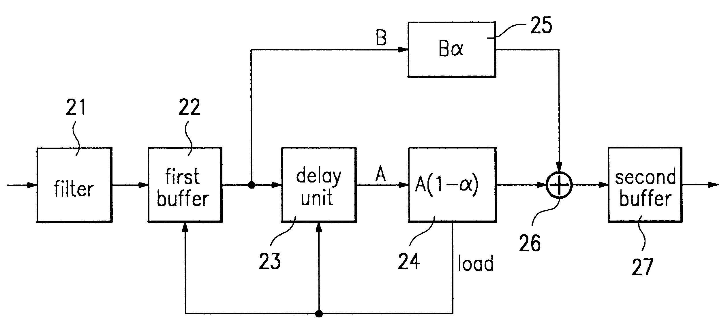
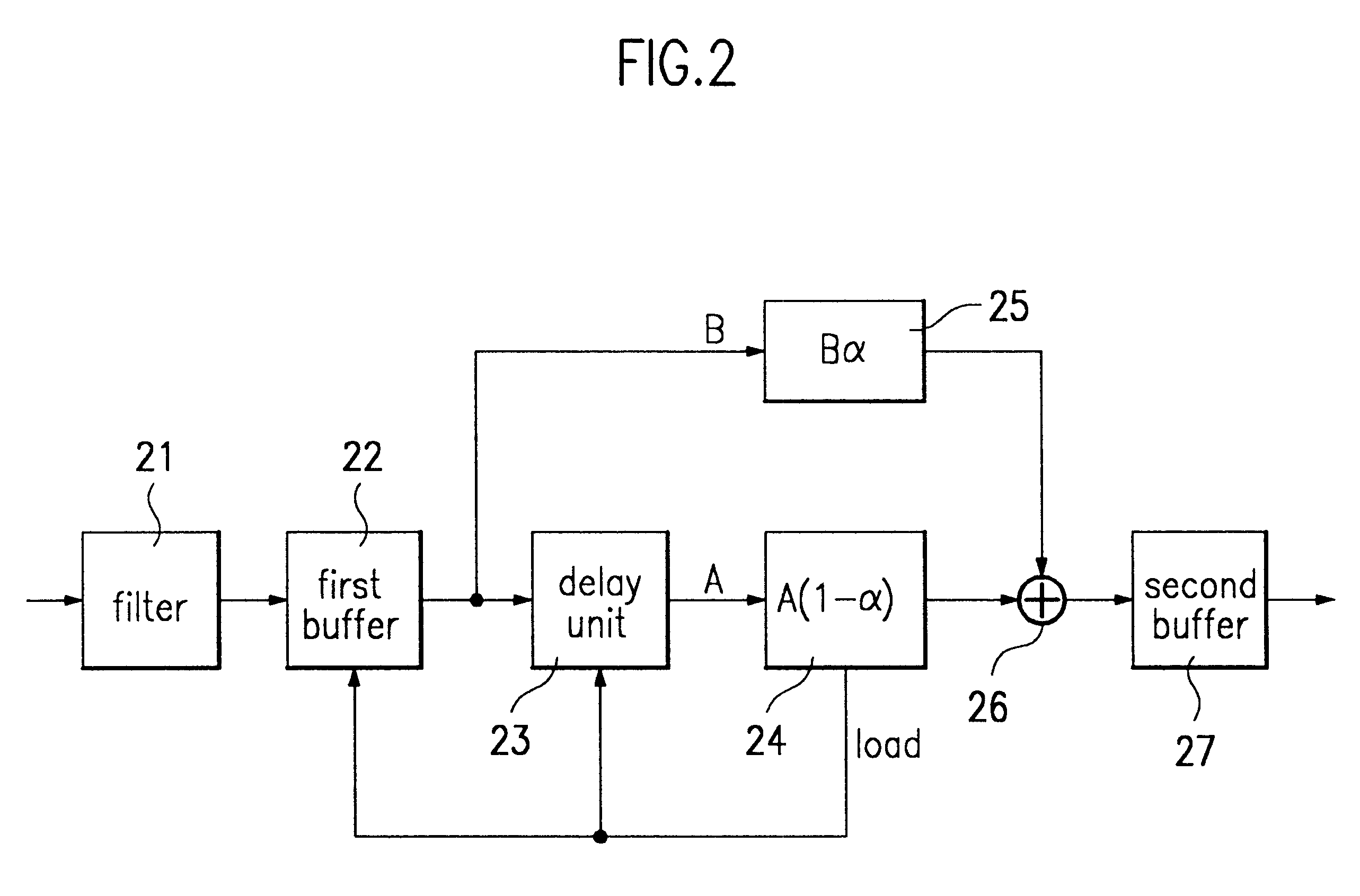
FIG. 2 is a block diagram of a video format converter according to one embodiment of the present invention.

Referring to FIG. 2, the video format converter includes a filter 21, a first buffer 22, a delay unit 23, a first operation unit 24, a second operation unit 25, an adder 26, and a second buffer 27. The filter...


PUM


Abstract

A video format converter for converting resolution of an input digital image to a different resolution includes an adder for adding the number of input pixels L to a feedback value, a modulo operation unit for allowing an output value of the adder as a numerator value to be feedback to the adder if the output value of the adder is smaller than the number of output pixels, but outputting a load signal so that a new data is loaded into them if the output value of the adder is greater than the number of output pixels M, and at the same time for outputting the remainder divided the output value of the adder by the number of output pixels to the adder, and a divider for performing division using the output value of the modulo operation unit as a numerator value and the number of output pixels as a denominator value and for outputting the resultant value as a weighted value alpha. Since the video format converter has a simple structure, a small amount of hardware can be realized. Also, since there are provided various input / output formats, it is not necessary to correct hardware due to a newly added format. Since differences in color coordinate sampling and scanning types as well as format size are considered, all kinds of format conversion can be realized without addition of a separate hardware.

Description

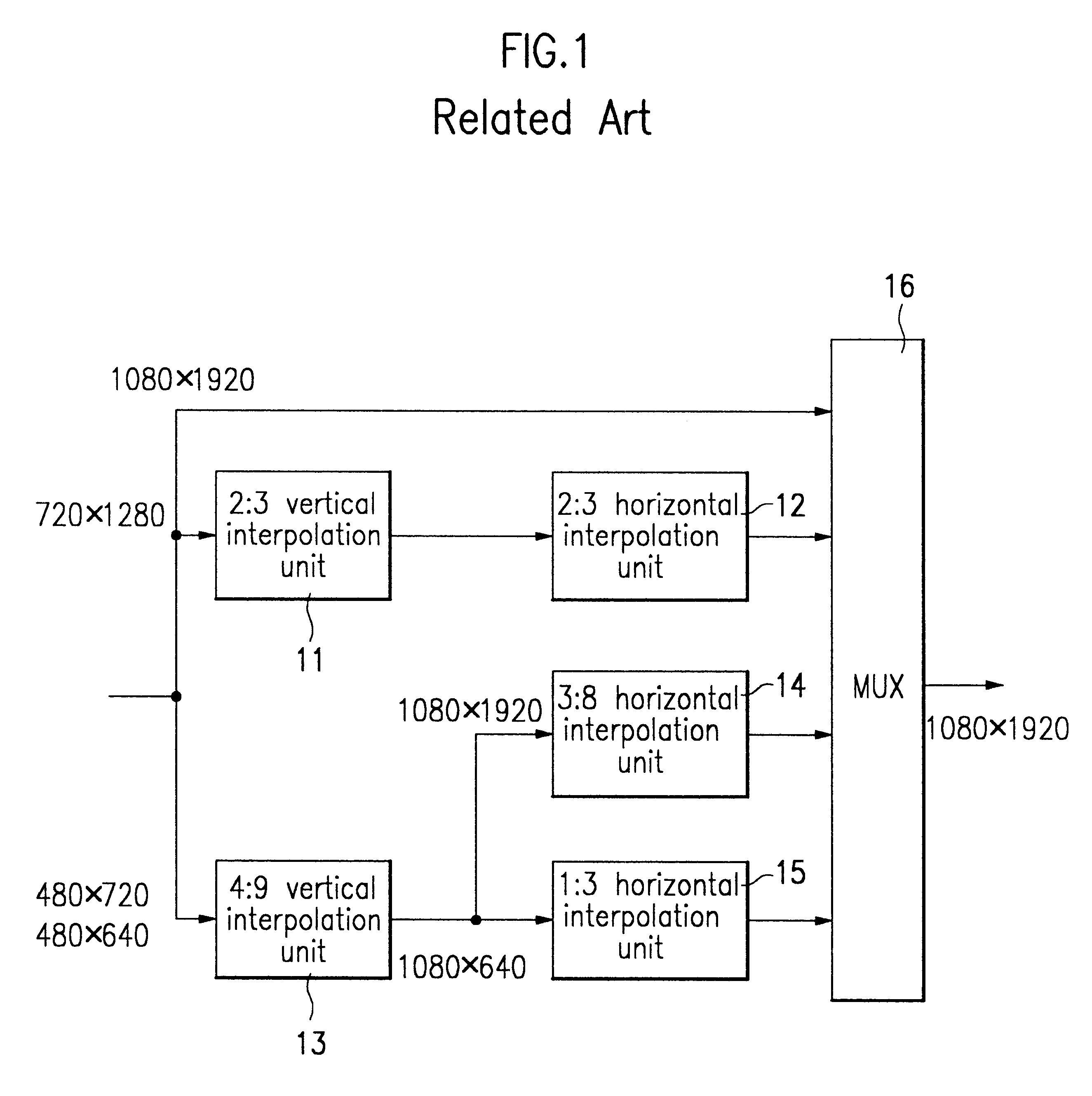
1. Field of the InventionThe present invention relates to a digital video processor and more particularly to an apparatus for converting resolution of an input digital image to a different resolution.2. Discussion of Related ArtA digital TV receives images of various types and resolution (or picture quality) such as a high definition grade and a standard definition grade. Also, it is expected that there are provided various types of display devices in a digital TV, such as an existing cathode ray tube (CRT) TV or projection TV adapted to an interlaced scanning type, and a liquid crystal display (LCD) and plasma display panel (PDP) adapted to a sequential scanning type. Thus, a digital TV requires a format converter which converts the type and size of images in compliance with the format of the display device.FIG. 1 is a block diagram of a general format converter, in which a plurality of format converters are used in parallel to convert various input formats to a desired output form...

Claims


Application Information

Patent Timeline
Patent Type & Authority Patents(United States)
IPC IPC(8): H04N7/01
CPCH04N7/0135H04N7/01
Inventor HAN, DONG IL
Owner LG ELECTRONICS INC
Learn More