Method and apparatus for optimizing operation points of a tunable laser

a laser and operation point technology, applied in the direction of laser details, laser output parameters control, semiconductor lasers, etc., can solve the problems of large quantities of unnecessary data, decisive drawbacks of processes, and high time-consuming measuring processes

Inactive Publication Date: 2003-01-07
COMMSCOPE TECH LLC
View PDF9 Cites 47 Cited by
  • Summary
  • Abstract
  • Description
  • Claims
  • Application Information

AI Technical Summary

Problems solved by technology

However, the process has decisive drawbacks.
The measuring processes are highly time-consuming and also generate large quantities of unnecessary data.
This makes it difficult to subsequently check or adjust the setting and / or the calibration of lasers that have already been installed in operation.

Method used


Image

  • Method and apparatus for optimizing operation points of a tunable laser
  • Method and apparatus for optimizing operation points of a tunable laser
  • Method and apparatus for optimizing operation points of a tunable laser

Examples


first embodiment

There has been described in the aforegoing a first embodiment where the sensing device includes a monitor detector.

second embodiment

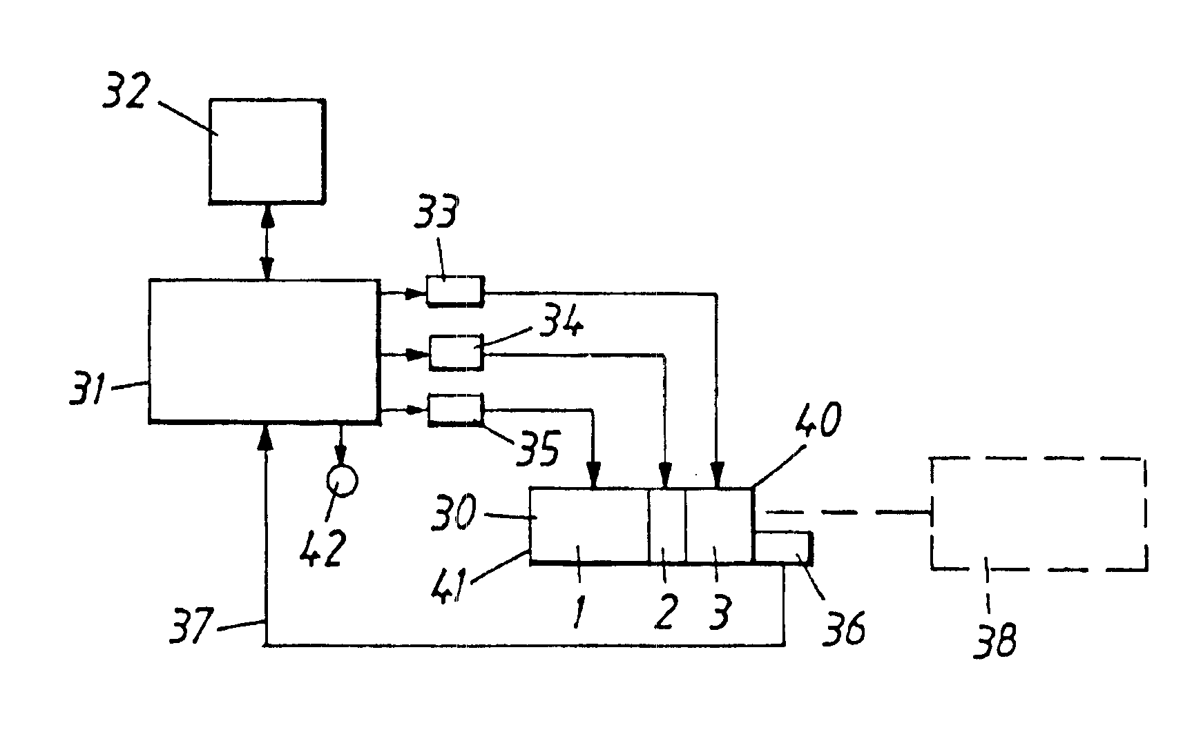
According to the invention, the sensing device includes, instead, a sensing circuit which is adapted to detect the voltage that prevails across the different laser sections when different amounts of current are injected into said sections 1, 2, 3. The detection circuit is firmly connected to the laser and is caused to measure the voltage across the various laser sections 1, 2, 3 for different combinations of laser section control. Signals delivered by the detection circuit at different control combinations are sent to the control unit 31.

When the laser is controlled with current and the laser goes through a mode jump, a discontinuity will occur in the voltage across one or more of the laser sections.

third embodiment

According to the invention, said sensing device includes a sensing circuit which is adapted to detect the current that flows through the different laser sections when a voltage is applied to said sections 1, 2, 3. The detection circuit is firmly connected to the laser and is caused to measure the current that passes through the various laser sections 1, 2, 3 with different combinations of voltage control across said sections. Signals delivered by the detection circuit in response to different control combinations are sent to the control unit 31.

It appears that when the laser is controlled with voltage and the laser goes through a mode jump, a discontinuity will occur in the current that flows through one or more of the laser sections.

The circuit for detecting the voltage across the laser sections, or the current that passes therethrough, can be integrated in a known manner in the drive circuits 33-35 exemplified above as current generators. Alternatively, the detection circuits may ...


PUM


Abstract

A method of optimizing the operation point of a laser, including characterizing the laser and controlling the different laser sections by varying the currents injected into the respective laser sections. The method includes sensing discontinuities that occur at mode jumps in a signal by utilizing a detection device that is firmly connected to the laser. Control of the different laser sections is effected by means of a control unit. Different control current combinations and the signal delivered by the detection device are provided to the control unit, which causes the control unit to detect the mode plane of the laser. At least a part of a mode plane, or several mode planes, are stored in a memory connected with the control unit, and the control unit controls the different laser sections so that the laser will operate at the desired operation point.

Description

1. Field of the InventionThe present invention relates to a method of optimizing the operation points of lasers, and also to means for this end. More, specifically, the invention relates to a method of optimization that does not require the aid of external equipment as a reference.2. Description of the Related ArtTuneable semiconductor lasers include several different sections through which current is injected. The lasers typically have three or more sections. The wavelength, power and mode purity of the lasers can be controlled, by adjusting the current injected into the various sections. Mode purity implies that the laser shall be tuned to an operation point, i.e. tuned to a combination of the three or four injected drive currents, which is characterized in that the laser is distanced from a combination of the drive currents where so-called mode jumps take place and where lasering is stable and where sidemode suppression is high.Special wavelength controls are required with differ...

Claims


Application Information

Patent Timeline
Patent Type & Authority Patents(United States)
IPC IPC(8): H01S5/00H01S5/0683H01S5/068H01S5/0625H01S5/0687H01S5/06
CPCH01S5/06808H01S5/0683H01S5/0014H01S5/0617H01S5/0625H01S5/0687H01S5/06256
Inventor BROBERG, BJORNANDERSSON, LARS
Owner COMMSCOPE TECH LLC
Why Eureka
Try Eureka