High power density/limited DC link voltage synchronous motor drive

a synchronous motor and high power density technology, applied in the direction of dynamo-electric converter control, dynamo-electric brake control, dynamo-electric gear control, etc., can solve the problems of affecting the winding included in the motor drive system can be large and heavy, and the limit of the inverter output ac voltage range can vary, so as to optimize the performance of the motor drive system

Inactive Publication Date: 2006-06-01
HONEYWELL INT INC
View PDF20 Cites 26 Cited by
  • Summary
  • Abstract
  • Description
  • Claims
  • Application Information

AI Technical Summary

Benefits of technology

[0014] Embodiments of the present invention are directed to a method and an apparatus for optimizing performance of a motor drive system. According to a first aspect of the present invention, a method of optimizing performance of a motor drive system comprises: selecting a property for a rated operation point; selecting inverter system characteristics and motor characteristics such that a motor drive system including an inverter system having the selected inverter system characteristics operatively connected to a motor having the selected motor characteristics will have a rated operation point exhibiting the property; providing an inverter system having the selected inverter system characteristics; operatively connecting a motor having the selected motor characteristics to the i...

Problems solved by technology

A motor drive system usually needs to accommodate various input DC bus voltage ranges, which ultimately cause variations in the limits of the inverter output AC voltage range.
The variability in inverter output AC voltage range and load conditions impacts motor drive system performance.
The winding included in a motor drive system can be large and heavy.
Installing, reinstalling, or replacing the winding inside the motor is a difficult task.
However, in many applications such as the more electric aircraft, the DC bus voltage that can be used to drive high power motor drive systems is limited.
In these applications, separate design optimization of mot...

Method used


Image

  • High power density/limited DC link voltage synchronous motor drive
  • High power density/limited DC link voltage synchronous motor drive
  • High power density/limited DC link voltage synchronous motor drive

Examples


Embodiment Construction

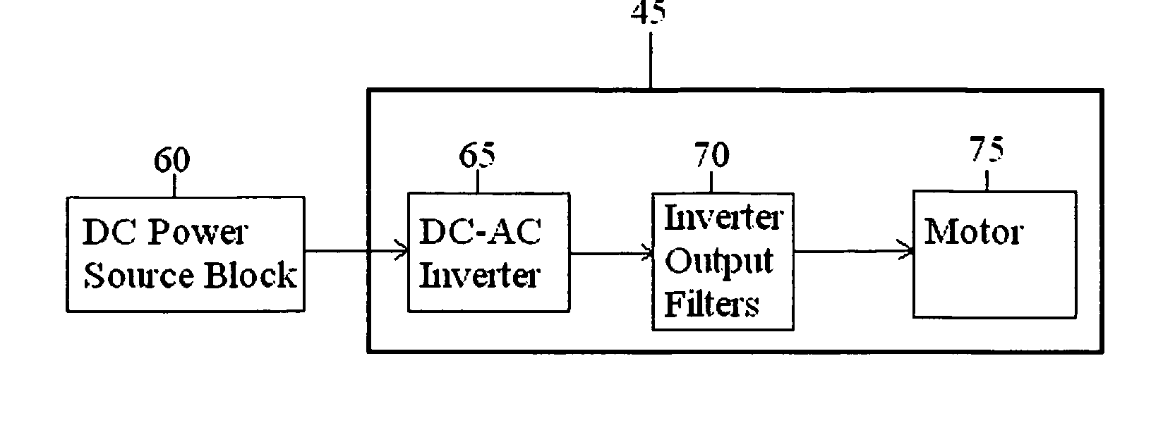
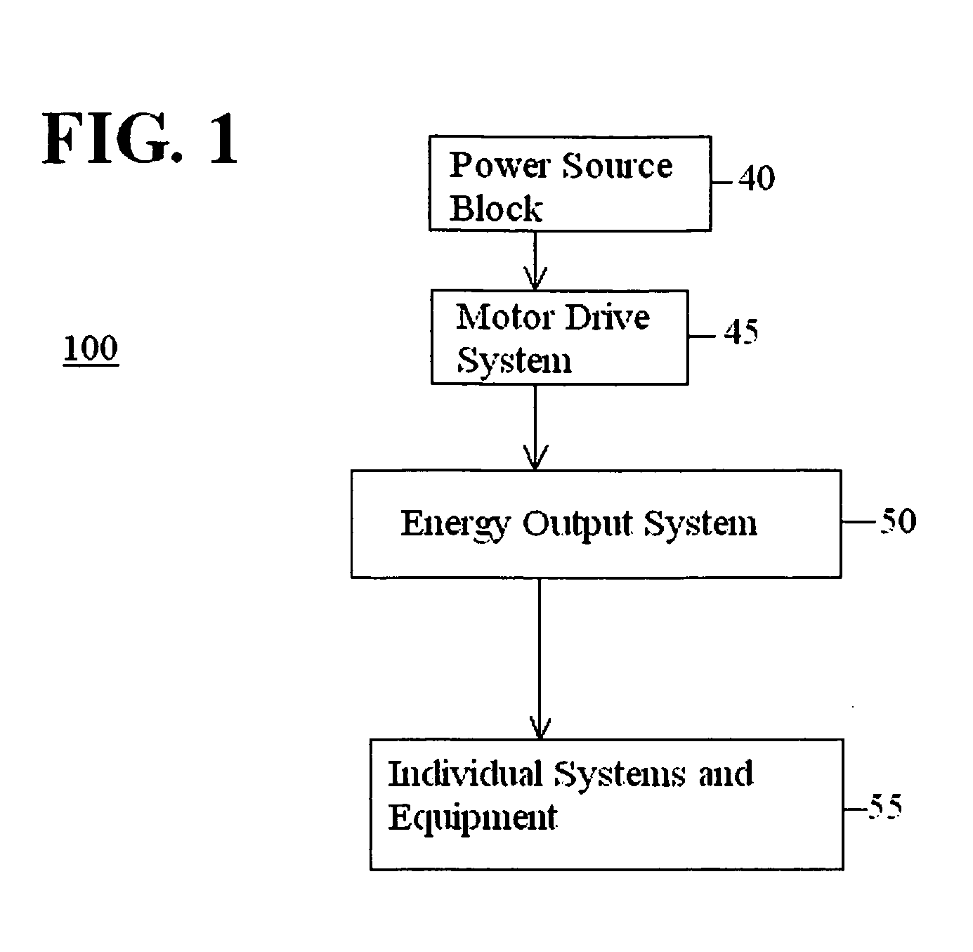
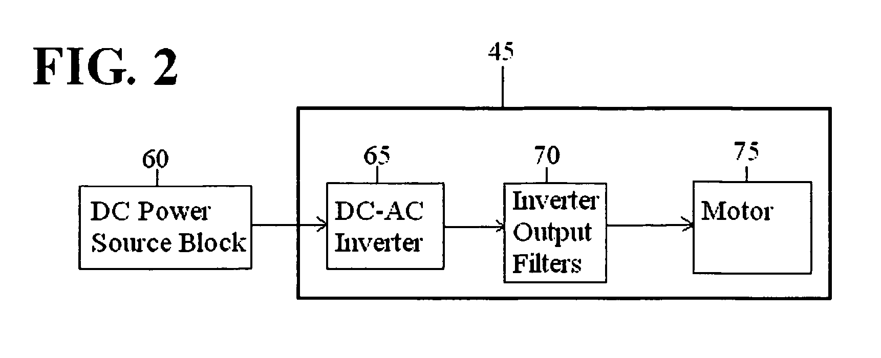
[0034] Aspects of the invention are more specifically set forth in the accompanying description with reference to the appended figures. FIG. 1 is a block diagram of an electrical / mechanical system containing a motor drive system with design / control optimization according to an embodiment of the present invention. The electrical / mechanical system 100 illustrated in FIG. 1 includes the following components: a power source block 40; a motor drive system 45 with design / control optimization; an energy output system 50; and individual systems and equipment 55. Operation of the electrical / mechanical system 100 in FIG. 1 will become apparent from the following discussion.

[0035] Electrical / mechanical system 100 may be associated with systems with electrical and mechanical components such as a cabin air compressor system, a heating system, a traction system, etc., in an aircraft, a ship, a train, a laboratory facility, etc. Power source block 40 provides electrical power to motor drive syste...


PUM


Abstract

A method and an apparatus optimize performance of a motor drive system. The method according to one embodiment comprises: selecting a property for a rated operation point; selecting inverter system characteristics and motor characteristics such that a motor drive system including an inverter system having the selected inverter system characteristics operatively connected to a motor having the selected motor characteristics will have a rated operation point exhibiting the property; providing an inverter system having the selected inverter system characteristics; operatively connecting a motor having the selected motor characteristics to the inverter system; and minimizing current of the motor drive system including the motor operatively connected to the inverter system in entire operating range of the motor drive system.

Description

CROSS REFERENCE TO RELATED APPLICATION [0001] The present application claims priority under 35 USC §119(e) to U.S. Provisional Application No. 60 / 631,429 filed Nov. 30, 2004, which is hereby incorporated by reference herein in its entirety.BACKGROUND OF THE INVENTION [0002] 1. Field of the Invention [0003] The present invention relates to motor drive systems, and more particularly to a technique for design / control of a motor drive system including a DC-AC inverter and a synchronous motor. [0004] 2. Description of the Related Art [0005] Large vehicles such as aircraft and ships include a multitude of electrical and mechanical systems that perform complex tasks and require large amounts of energy. Synchronous motor drive systems are suitable for large vehicles. Synchronous motor drives are energy conversion systems that can produce large amounts of energy at high power and high speed, as needed for complex equipment onboard large vehicles. Synchronous motor drive systems are especiall...

Claims


Application Information

Patent Timeline
IPC IPC(8): H02P27/04
CPCH02P6/181H02P6/182H02P25/021H02P27/02H02P25/024
Inventor ZHOU, GEORGEMA, JACKWANG, ZHENG
Owner HONEYWELL INT INC
Why Eureka
Try Eureka