
Method and Apparatus for Determining an Operating Point of a Work Machine

a technology of work machine and operating point, which is applied in the direction of mechanical equipment, machines/engines, instruments, etc., can solve the problems of inability to meet the condition in practice, difficulty or even impossible, and inability to arithmetically determine the delivery ra

Active Publication Date: 2012-05-10
KSB AG
View PDF6 Cites 23 Cited by
  • Summary
  • Abstract
  • Description
  • Claims
  • Application Information

AI Technical Summary

Benefits of technology

[0011]The object on which the invention is based is to make available a method and an apparatus by means of which a less complicated, reliable determination and, where appropriate, monitoring of the current operating point of a work machine and / or of an asynchronous motor driving the latter are possible.
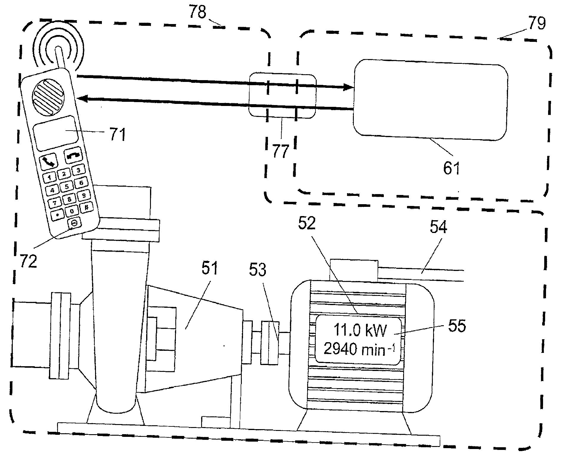
[0023]The shaft output and / or delivery rate can be determined from the rotational speed by means of the rotational speed / torque dependence. Measurement of electrical variables is dispensed with, with the result that the outlay for carrying out operating point determination is reduced considerably, as compared with conventional operating point determination based on electrical active power measurement. Likewise, as compared with direct measurement of the delivery rate, for example by means of ultrasonic throughflow measurement technology or magnetoinductive throughflow measurement technology, there is a considerable cost benefit, since the mechanical measurement variables used, namely pressure, differential pressure, force, vibration, solid-borne noise or airborne noise, are detected and processed in a more favorable way.
[0032]According to one especially reliable method, the drive rotational speed or shaft rotational speed is determined from measurement values of one or more pressure sensors for the purpose of determining the operating point of the pump, in particular the centrifugal pump. It is advantageous in this case if the pressure sensors are suitable for the dynamic measurement of pressures, in particular of pulsating pressures. The operating point of the pump, in particular a centrifugal pump, which is characterized by the shaft output and / or delivery rate is therefore determined solely from measurement values of one or more pressure sensors. One or more pressure sensors are employed on a centrifugal pump in order to detect the suction and / or ultimate pressure of a centrifugal pump. Pressure sensors, although provided for measuring static pressures, are also most suitable for the dynamic measurement of pressures. Tests have shown that standard pressure sensors detect pressures dynamically, and undamped, up to a frequency range of approximately 1 kHz. Such pressure sensors are capable of detecting pulsating pressures occurring within a centrifugal pump. The method according to the invention achieves sufficient accuracy for many applications when only one pressure sensor is used on the delivery side of the pump. In addition, a pressure sensor may be provided on the suction side of the pump. There is likewise provision for evaluating a pump differential pressure between the delivery side and suction side of the pump, obtainable by means of a differential pressure sensor. By virtue of the method according to the invention, the operating point can be determined cost-effectively, without the use of additional sensors, solely from one or more pressure sensor signals.
[0041]There is a considerable cost benefit, as compared with direct measurement of the delivery rate, for example, by means of ultrasonic throughflow measurement technology or magnetoinductive throughflow measurement technology. Outlay and costs are also minimized, as compared with determining the delivery rate on the basis of electrical active power measurement.
[0048]The apparatus according to the invention differs from what is conventional in industrial terms, as mentioned, in that it makes it possible to detect the pulsating component of a pressure signal, while at the same time having high dynamics. This ensures that the frequency of the pulsating pressure component is determined exactly in a relevant frequency range. The apparatus advantageously comprises an input for signal components of up to approximately 500 Hz, a limit frequency for an input filter being correspondingly higher.
[0051]In this case, the amplitude of the pulsating pressure component is relatively low. In a concrete example, the amplitude of the pulsating signal component amounts to less than 1% of the pressure. The apparatus processes the measurement range of the pressure signal with correspondingly high resolution, so that the pressure pulsation can be evaluated satisfactorily according to analog / digital conversion in spite of the low amplitude, that is to say the rotational sound frequency can be determined. The apparatus according to the invention thus makes it possible to determine an operating point of a pump reliably.

Problems solved by technology

Indirect determination of the delivery rate arithmetically presents additional difficulties.
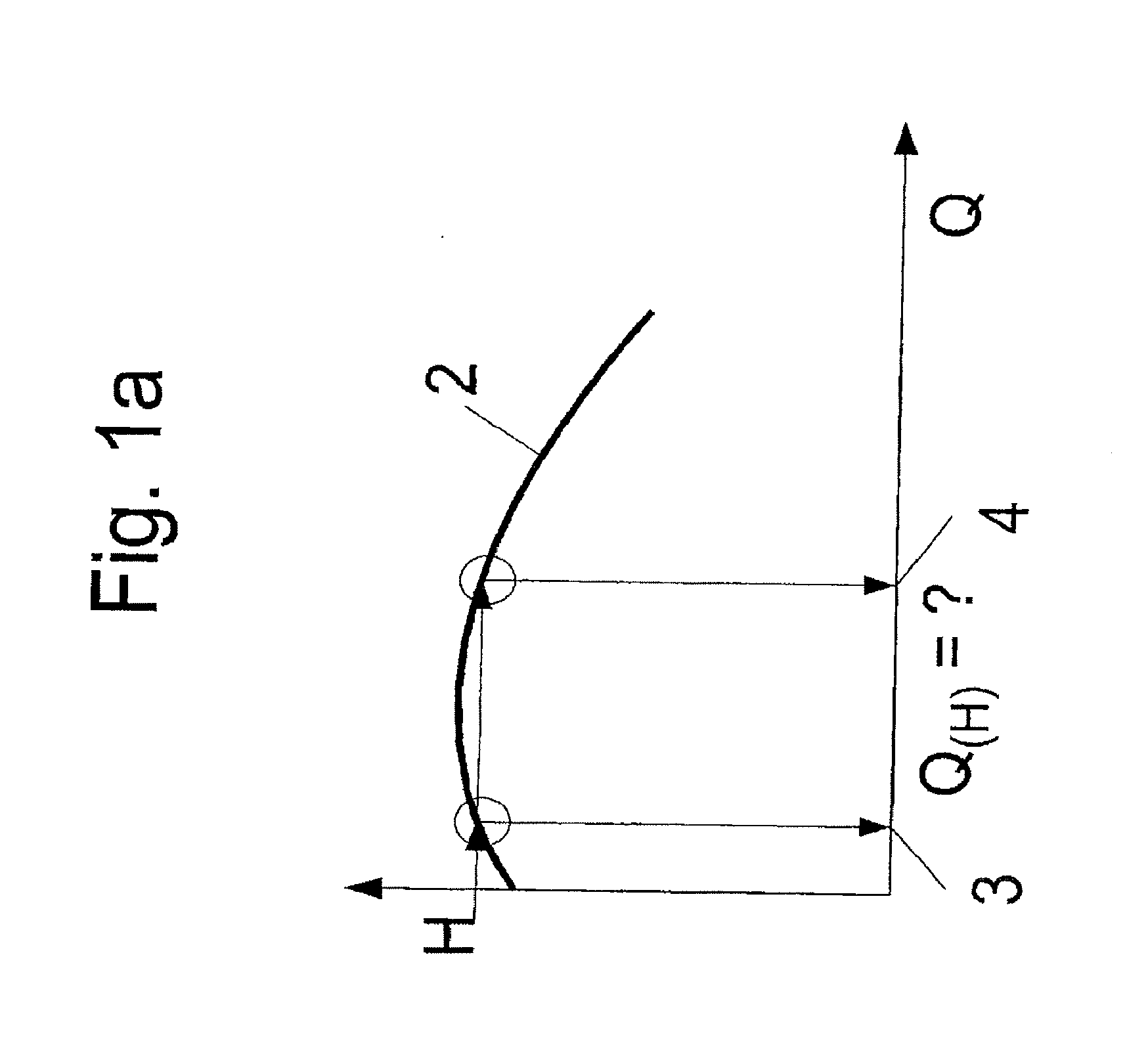
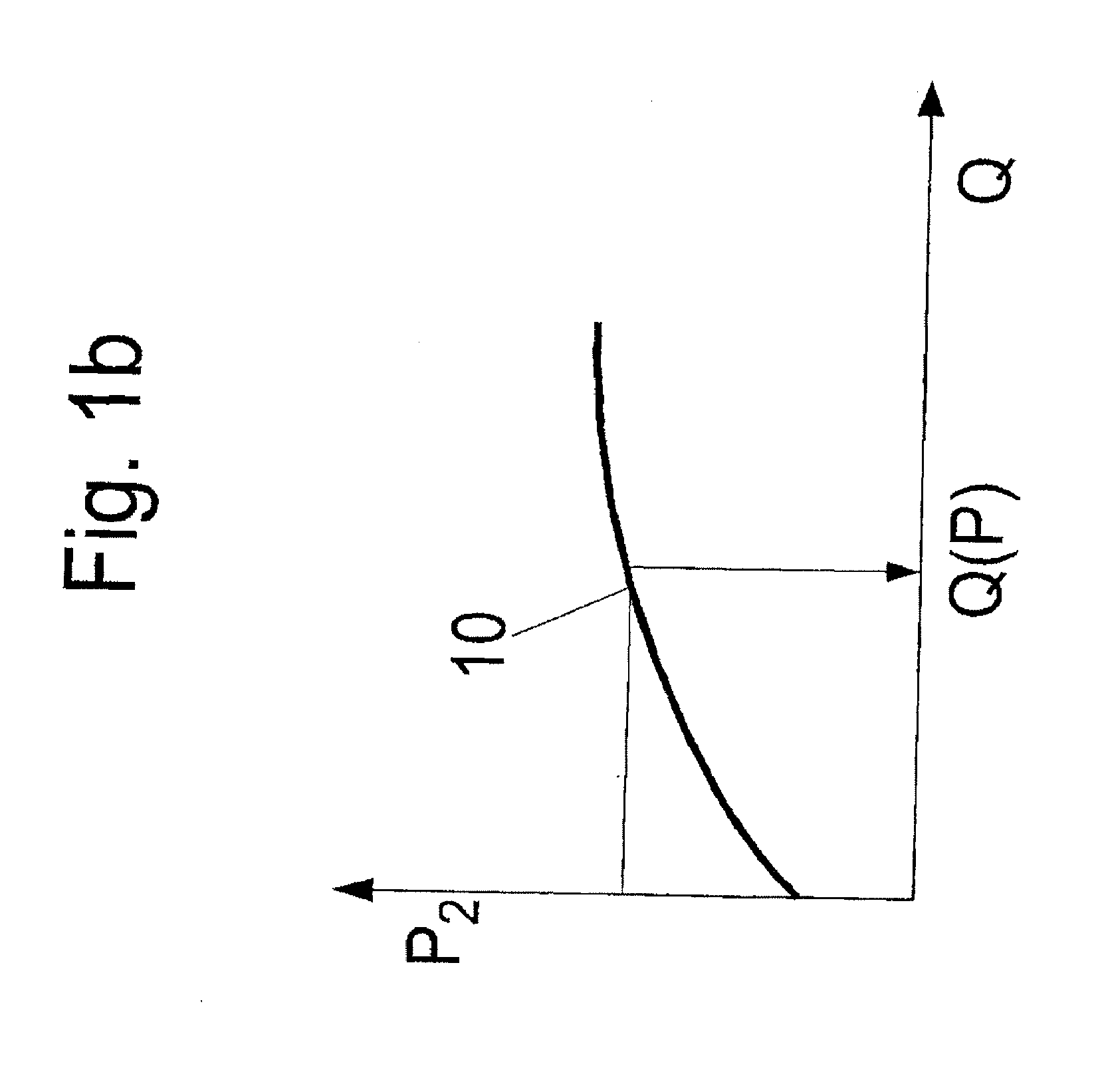
If, for example, a delivery rate is derived from the values of a delivery flow / delivery head characteristic curve, a Q-H characteristic curve, in which the delivery head H is plotted against the delivery flow, or of a delivery flow / power characteristic curve, a Q-P characteristic curve, in which the power P is plotted against the delivery flow Q, this is difficult or even impossible in those situations where there is a flat or a discontinuously rising Q-H characteristic curve or Q-P characteristic curve.
This condition is often not fulfilled in practice.
The same problem also arises when the delivery flow Q is to be determined by means of a measured power input from the delivery flow / power characteristic curve, the Q-P characteristic curve.
This arrangement has a complicated configuration.
This method has proved to be unsuitable in industrial practice.
It is a particular disadvantage, even when the active power input of an asynchronous motor is measured conventionally by active power meters and current transformers, that it is absolutely necessary that such an arrangement is installed by specialized electricians.

Method used


Image

  • Method and Apparatus for Determining an Operating Point of a Work Machine
  • Method and Apparatus for Determining an Operating Point of a Work Machine
  • Method and Apparatus for Determining an Operating Point of a Work Machine

Examples


Embodiment Construction

[0073]FIG. 1a shows a delivery flow / delivery head characteristic curve 2, what is known as a Q-H characteristic curve, of a centrifugal pump. According to the prior art, a delivery head H of the pump can be determined from a pressure difference measured between the delivery side and suction side of the centrifugal pump, and the operating point of the centrifugal pump can be determined via the delivery flow / delivery head characteristic curve 2. However, determining an operating point in this way is insufficient in a range of smaller delivery flows in which the delivery flow / delivery head characteristic curve 2 is ambiguous or unstable. Such a characteristic curve which is unstable has the effect that, in the case of specific measured pressure differences in relation to a specific delivery head H, there are two delivery flow values 3, 4. A delivery rate Q(H) of the centrifugal pump therefore cannot be inferred unequivocally.

[0074]FIG. 1b shows a delivery flow / power characteristic curv...


PUM


Abstract

Method and apparatus for determining an operating point of a work machine and / or asynchronous motor driving the same, the operating point being characterized by the power consumed by and / or output rate of the machine, in which one or more operating point-dependent measurement variables of the machine are detected by sensors, and the measured values are evaluated and / or stored during operation of the machine. The operating point is determined without using electric measurement variables of the motor by determining a frequency linearly proportional to the fundamental tone of the machine through signal analysis, especially frequency analysis of a measured mechanical variable selected from pressure, differential pressure, power, vibration, and solid-borne or air-borne sound. From this, the rotational speed of the driving machine is determined, and the operating point characterized by the power consumed by and / or output rate of the machine is determined utilizing the rotational speed / torque relationship of the motor.

Description

CROSS REFERENCE TO RELATED APPLICATIONS[0001]This application is a continuation-in-part of international patent application no. PCT / EP2010 / 055621, filed Apr. 27, 2010, designating the United States of America and published in German on Nov. 25, 2010 as WO 2010 / 133425, the entire disclosure of which is incorporated herein by reference. Priority is claimed based on Federal Republic of Germany patent application no. DE 10 2009 022 107.7, filed May 20, 2009, the entire disclosure of which is likewise incorporated herein by reference.BACKGROUND OF THE INVENTION[0002]The invention relates to a method for determining an operating point of a work machine and / or of an asynchronous motor driving the latter, a power input of the work machine and / or its delivery rate characterizing an operating point, one or more operating point-dependent measurement variables of the work machine being detected by one or more sensors, and the measurement values being evaluated and / or stored while the work machi...

Claims


Application Information

Patent Timeline
IPC IPC(8): G01H13/00
CPCF04D15/0088F04D15/0094
Inventor EMDE, CHRISTOPHLAUE, STEFANSILOVIC, MARJAN
Owner KSB AG
Learn More