Electric double-layer capacitor having a laminated overcoat

a double-layer capacitor and laminated overcoat technology, applied in the direction of electrolytic capacitors, liquid electrolytic capacitors, cell components, etc., can solve the problems of affecting the sealing property of the fused innermost surface of the laminated overcoat for preventing air ingress, and the drawback of a larger thickness of edl

Inactive Publication Date: 2003-01-14
NEC CORP
View PDF16 Cites 17 Cited by
  • Summary
  • Abstract
  • Description
  • Claims
  • Application Information

AI Technical Summary

Problems solved by technology

In this case, especially in the case of using bolts, the EDLC has the drawback of a larger thickness.
In the conventional EDLC having the laminated structure, however, there is a problem of ingress of air, which damages the electric property of the EDLC obtained by the laminated structure.
It is difficult to secure the sealing property of the fused innermost surface of the laminated overcoat for prevention of the ingress of air, especially in the vicinity of the external terminals.
This degrades the reliability of the EDLC having the laminated structure to result in reduction of the long-term stability of the electric property.

Method used


Image

  • Electric double-layer capacitor having a laminated overcoat
  • Electric double-layer capacitor having a laminated overcoat
  • Electric double-layer capacitor having a laminated overcoat

Examples


first embodiment

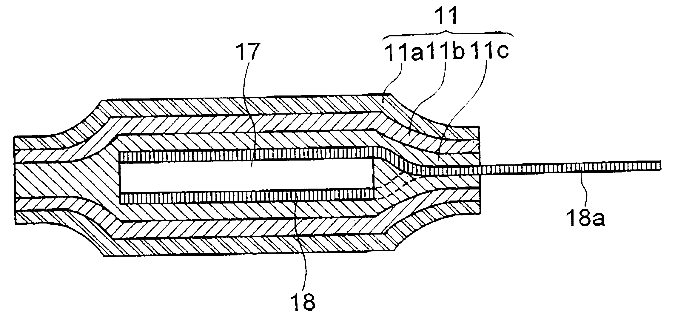
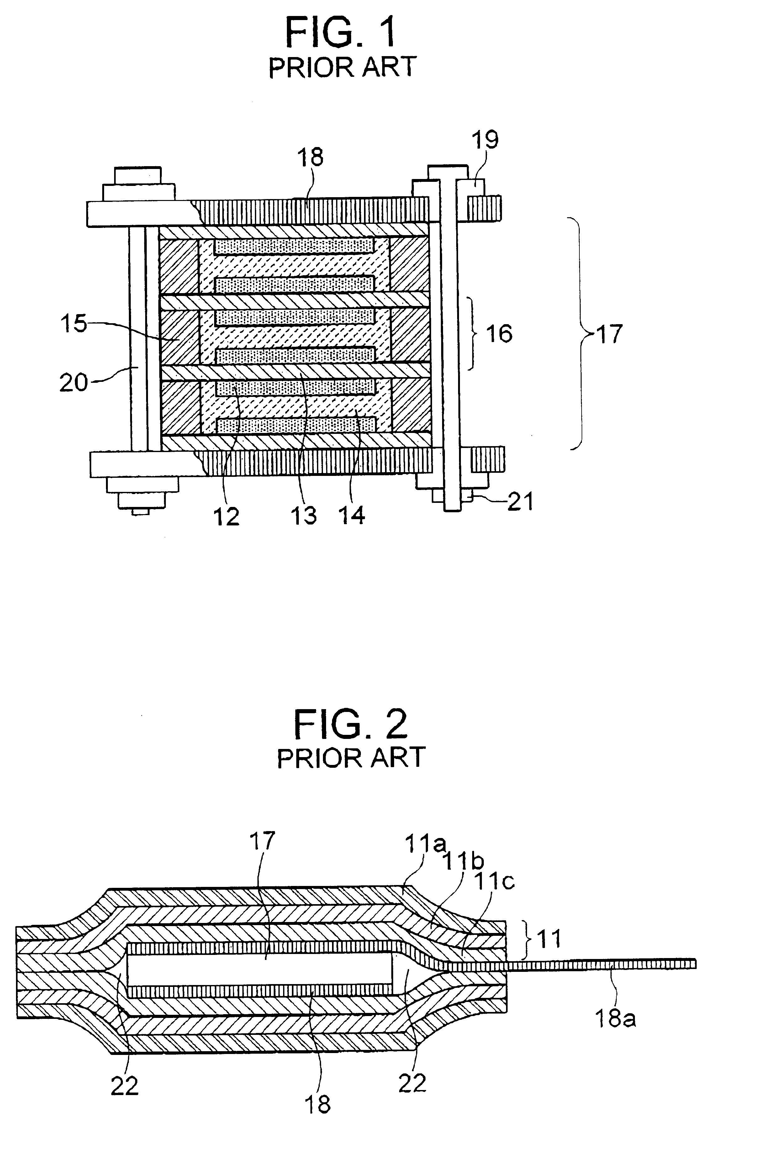
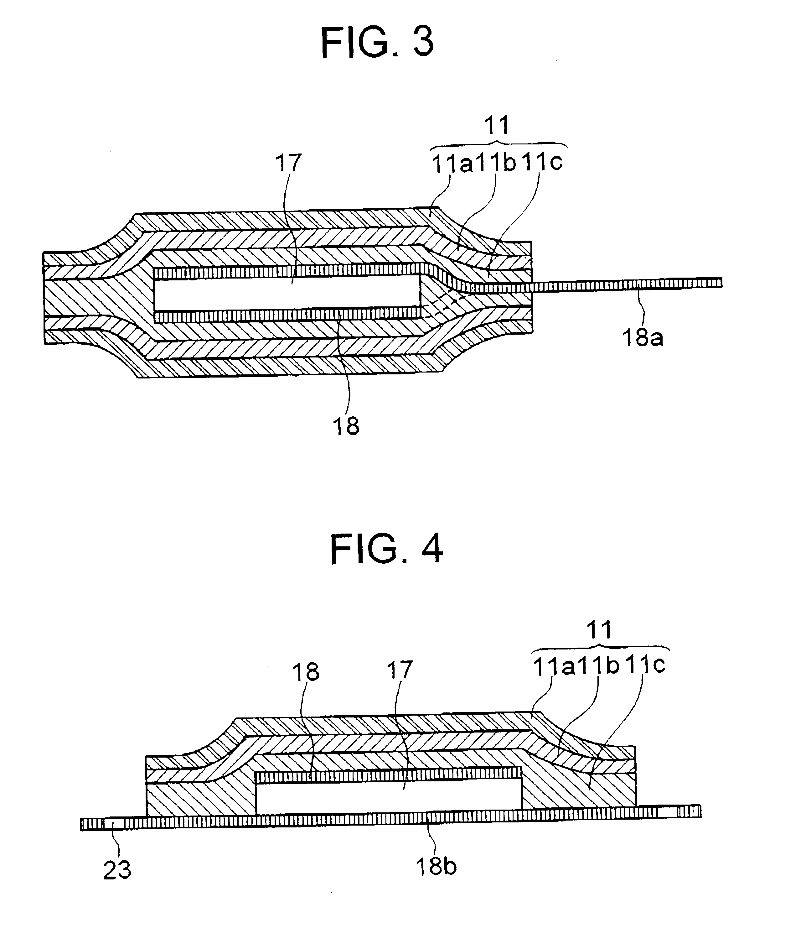
Referring to FIG. 3, an EDLC according to the present invention has a laminated structure and includes a stacked body (EDLC body) 17, a pair of terminal plates 18 sandwiching therebetween the staked body 17, and a laminated overcoat 11 having an innermost surface fused onto the stacked body 17 and the terminal plates 18 substantially without forming a gap. The laminated overcoat 11 is formed by fusing a pair of laminated films at a high temperature using an equal-pressure pressing machine while evacuating the internal of the laminated overcoat 11.

The stacked body 17 includes one or more of basic cells each including a separator, a pair of polarized electrodes sandwiching therebetween the separator, a pair of current collectors sandwiching therebetween the pair of polarized electrodes, a gasket disposed between the pair of current collectors for encircling the separator and the pair of polarized electrodes, and an electrolytic solution used for impregnating the separator and the pola...

second embodiment

Referring to FIG. 4, an EDLC according to the present invention includes a rectangular substrate 18b having a rigid or elastic property and holes therein at the four corners, a stacked body 17 disposed on the substrate 18b with a marginal area left at four sides of the stacked body 17, a terminal plate 18 formed on top of the stacked body 17, a laminated overcoat 11 covering the terminal plate 18, the stacked body and the marginal area of the substrate 18b except for the edge of the substrate 18b.

The laminated overcoat 11 has a three-layer structure as in the case of the first embodiment. The fused layer 11c is fused to the top and sides of the terminal plate 18, the sides of the stacked body 17 and the top surface of the marginal area of the substrate 18b substantially without forming a gap between the same and these encapsulated elements.

The substrate 18b formed as a part of the encapsulating member and having a rigidity or flexibility exerts a suitable mechanical strength against...


PUM


Abstract

An electric double-layer capacitor (EDLC) has a laminated overcoat encapsulating a stacked body including a plurality of basic cells and a pair of terminals sandwiching therebetween the stacked body. The innermost film of the laminated overcoat is thermally fused onto the exposed surfaces of the terminal plates and the stacked body substantially without a gap. The fusing step is conducted by an equal-pressure pressing using a hot water while the internal of the laminated overcoat is evacuated.

Description

(a) Field of the InventionThe present invention relates to an electric double-layer capacitor (EDLC) having a laminated overcoat and, more particularly to such an EDLC having excellent electric characteristics and a longer lifetime.(b) Description of the Related ArtThe EDLC uses an electric double layer structure generated at the interfaces between polarized electrodes and an electrolytic solution for storing electric charge therein. The EDLC has the advantages of a lower thickness of the double-layer structure as low as several nanometers and capability of having a larger capacitance by using the polarized electrodes made of a material having a larger surface area, such as activated carbon.EDLCs described in Patent Publications JP-2054380 and JP-A-57-60828 have polarized electrodes made of aluminum foils for achieving a larger capacitance and a lower internal resistance. These EDLCs are now being used for a variety of applications requiring a large electric power, such as for a hyb...

Claims


Application Information

Patent Timeline
Patent Type & Authority Patents(United States)
IPC IPC(8): H01G9/00H01G9/08H01G11/00H01G9/10H01G11/74H01G11/78H01G11/80H01G11/82H01G11/84
CPCH01G9/08H01G9/155Y02E60/13H01G11/78H01G11/80H01G11/74
Inventor SAITO, TAKASHIKASAHARA, RYUICHI
Owner NEC CORP
Why Eureka
Try Eureka