Electrode for electric double-layer capacitor, and slurry for forming the same

a technology of electric double-layer capacitors and electrodes, which is applied in the direction of conductive materials, non-conductive materials with dispersed conductive materials, electrical apparatuses, etc., can solve the problems of inability to reduce oxidizing reaction may occur in the positive electrode, and measures are incapable of reducing contact resistance to an expected extent. , to achieve the effect of high strength

Inactive Publication Date: 2006-08-22
HONDA MOTOR CO LTD
View PDF9 Cites 9 Cited by
  • Summary
  • Abstract
  • Description
  • Claims
  • Application Information

AI Technical Summary

Benefits of technology

[0015]Accordingly, it is an object of the present invention to provide an electrode of the above-described type which is formed using a particular material including the above-described alkali-activated carbon as a main component and which is capable of increasing the electrostatic capacity of an electric double-layer capacitor of the above-described type and enhancing the durability of the capacitor.

Problems solved by technology

However, as a result of studies further advanced, it has been found that the rest potential of the alkali-activated carbon in an electrolyte is offset relatively largely toward an oxidizing reaction region from an ideal rest potential of the activated carbon, and for this reason, there is a possibility that an oxidizing reaction may be liable to occur in the positive electrode during charging, whereby the durability of the electric double-layer capacitor may be impeded.
However, the conventional measures are incapable of decreasing the contact resistance to an expected extent even with a high working cost.
However, the following problem is encountered: This meso-phase activated carbon is liable to be agglomerated in a slurry, because it has a high water-absorbing ability, and when an agglomeration has been produced, the thickness and density of the formed electrode are non-uniform, resulting in decreases not only in performance but also in strength of the electrode.

Method used


Image

  • Electrode for electric double-layer capacitor, and slurry for forming the same
  • Electrode for electric double-layer capacitor, and slurry for forming the same
  • Electrode for electric double-layer capacitor, and slurry for forming the same

Examples


embodiment i

[Embodiment I]

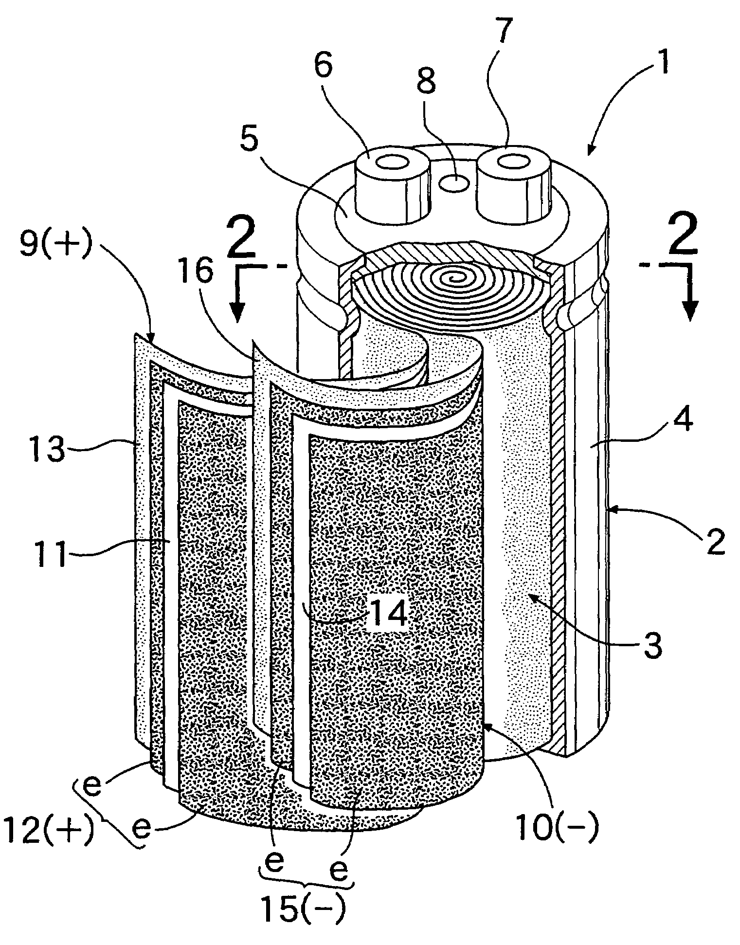
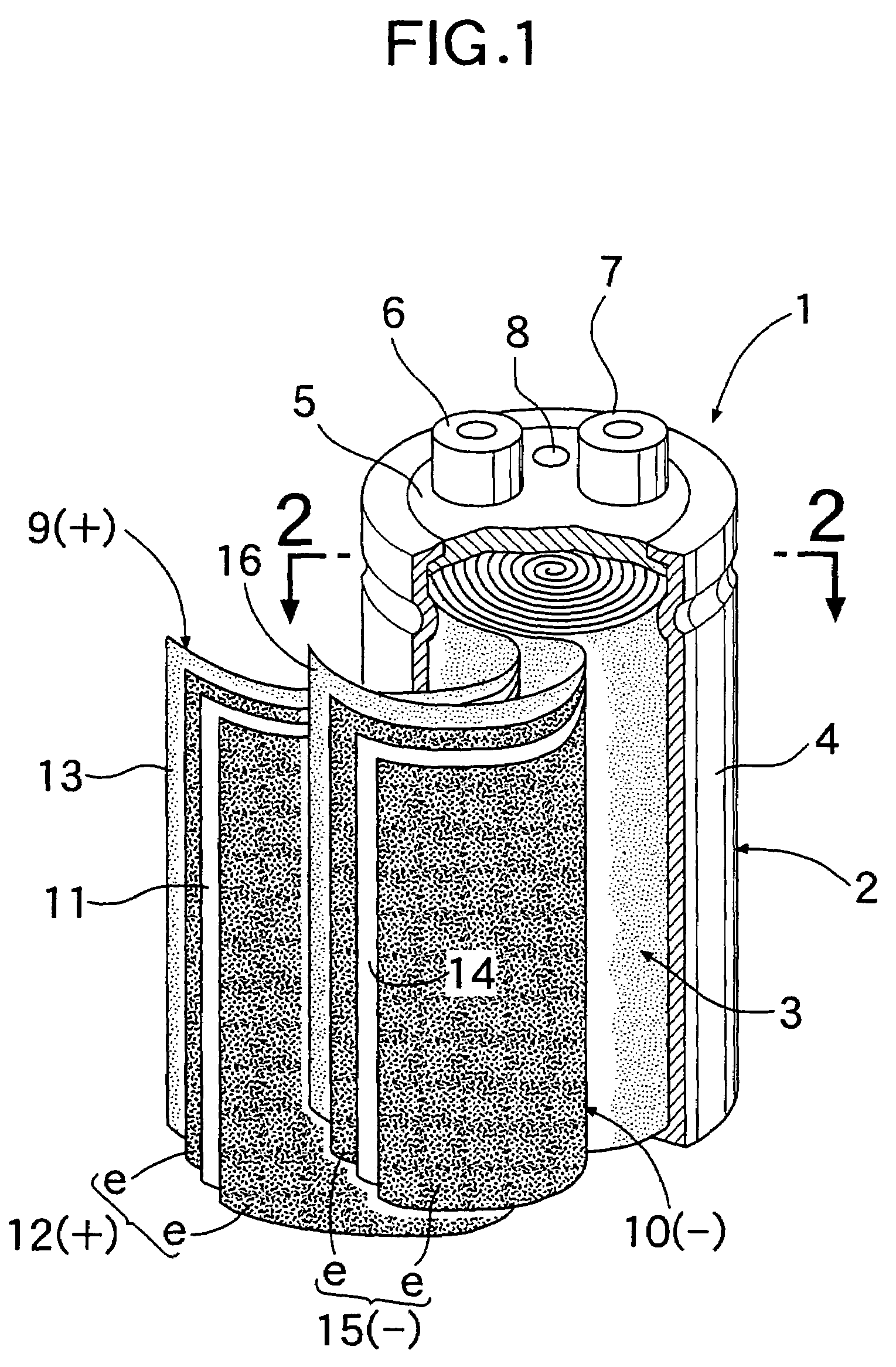
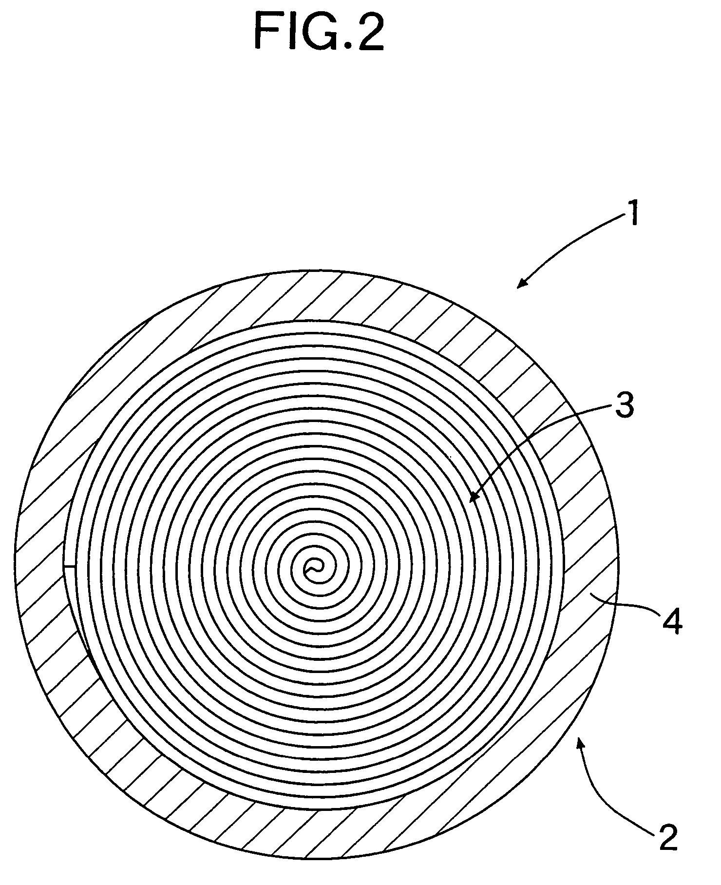
[0041]Referring to FIGS. 1 and 2, a cylindrical electric double-layer capacitor 1 includes a container 2 made of aluminum (Al), an electrode winding 3 accommodated in the container 2, and an electrolyte poured in the container 2. The container 2 is comprised of a bottomed cylindrical body 4, and a terminal plate 5 which closes an opening in one end of the body 4. Positive and negative terminals 6 and 7 and a safety valve 8 are provided on the terminal plate 5.

[0042]The electrode winding 3 has a positive electrode laminated band 9 and a negative electrode laminated band 10. The positive electrode laminated band 9 comprises a band-shaped current colletor 11 made of an aluminum foil and having band-shaped polarizing electrodes e affixed respectively to opposite surfaces thereof by a conductive adhesive, and a first separator 13 made of PTFE (polytetrafluoroethylene) and superposed onto one of the band-shaped polarizing electrodes e. A band-shaped positive electrode 12 whi...

embodiment ii

[Embodiment II]

[0058]Referring to FIGS. 8 and 9, a rectangular electric double-layer capacitor 17 includes a container 18 made of aluminum (Al), an electrode laminate structure 19 accommodated within the container 18, and an electrolyte poured into the container 18. The container 18 comprises a bottomed rectangular cylindrical body 20, and a terminal plate 21 which closes an opening in one end of the bottomed rectangular cylindrical body 20. Positive and negative terminals 22 and 23 are provided on the terminal plate 21.

[0059]The electrode laminate structure 19 has a plurality of positive electrode laminates 24 and a plurality of negative electrode laminates 25, which are arranged alternately. Each of the positive electrode laminates 24 comprises a positive electrode plate 27 comprised of polarizing electrodes e affixed respectively to opposite surfaces of a current colletor 26 made of an aluminum foil by an adhesive including a conductive filler, and a separator 28 made of PTFE (po...

example i

[0065]Eighty-seven % by weight of fibrous meso-phase activated carbon having a diameter of 5 to 30 μm and a length of 100 μm or less, 10% by weight of acetylene black having a particle size of 1 nm to 100 μm, and 3% by weight of a binder comprising a PTFE powder were blended together. The blend was subjected to an extrusion, thereby forming four extruded sheets having different thickness. The extruded sheets were subjected to one, three, five and seven runs of a rolling treatment, respectively, to form four sheet-shaped polarizing electrodes having the same thickness.

[0066]Table 1 shows the relationship between the thickness of the extruded sheets and the number of runs of the rolling treatment and the thickness of the sheet-shaped polarizing electrodes.

[0067]

TABLE 1Thickness ofNumber of runs of rolling treatmentextruded sheet (μm)OneThreeFiveSeven200180———247222180——304274222180—377339274222180Thickness of sheet-shaped polarizingelectrode (μm)

[0068]Each of the sheet-shaped polarizi...


PUM

PropertyMeasurementUnit
viscosityaaaaaaaaaa
particle sizeaaaaaaaaaa

Abstract

In an electric double-layer capacitor, a solution of a quaternary ammonium borofluoride compound in propylene carbonate is used as an electrolyte. The electrode includes alkali-activated carbon made using meso-phase pitch as a starting material, and a conductive filler having a rest potential smaller than that of the alkali-activated carbon in the electrolyte. The amount Fc of conductive filler incorporated in the electrode is set in a range of 10% by weight≦Fc≦40% by weight. Such electric double-layer capacitor has a large electrostatic capacity and excellent durability.

Description

CROSS-REFERENCE TO RELATED APPLICATION[0001]This application is a divisional application which claims the benefit of pending application Ser. No. 09 / 635,235, filed Aug. 9, 2000, now U.S. Pat. No. 6,800,222. The disclosure of the prior application is hereby incorporated herein by reference in its entirety.BACKGROUND OF THE INVENTION[0002]1. Field of the Invention[0003]The present invention relates to an electrode for an electric double-layer capacitor, and a slurry for forming the electrode.[0004]2. Description of the Related Art[0005]There is a conventionally known electric double-layer capacitor made using a solution of quaternary ammonium borofluoride compound in propylene carbonate as an electrolyte. Vapor-activated carbon having a turbulent structure is used as activated carbon in electrodes of the electric double-layer capacitor, namely, positive and negative electrodes.[0006]With the electric double-layer capacitor provided with the positive and negative electrodes made from t...

Claims


Application Information

Patent Timeline
Patent Type & Authority Patents(United States)
IPC IPC(8): H01M4/58C04B16/02H01B1/20H01G9/00H01G9/155
CPCH01G9/155Y02E60/13H01G11/34H01G11/38H01G11/86
Inventor NOGUCHI, MINORUIWAIDA, MANABUOKI, NAOHIKOKOMAZAWA, EISUKETAKESHITA, TAKAHIROMURAKAMI, KENICHI
Owner HONDA MOTOR CO LTD
Why Eureka
Try Eureka