Refrigeration system, and method of updating and operating the same

a refrigeration system and air conditioning technology, applied in refrigeration machines, refrigeration components, light and heating apparatus, etc., can solve the problems of difficulty in replacing connecting pipes with new pipes, and deterioration of hfc refrigeration oil

Inactive Publication Date: 2003-01-28
MITSUBISHI ELECTRIC CORP
View PDF17 Cites 25 Cited by
  • Summary
  • Abstract
  • Description
  • Claims
  • Application Information

AI Technical Summary

Problems solved by technology

In a case where the first connecting pipe CC and the second connecting pipe DD interconnecting the heat source unit AA and the indoor unit BB are lengthy and embedded in a structure, such as a pipe shaft or a ceiling, difficulty is encountered in replacing the connecting pipes with new pipes.
If a mineral oil is mixed into the HFC refrigeration oil, the HFC refrigeration oil becomes deteriorated.
Alternatively, if a CFC or HCFC is mixed into the HFC refrigeration oil, a chlorine component contained in the CFC or HCFC deteriorates the HFC refrigeration oil; otherwise, a chlorine component contained in sludge formed from a depleted substance of the CFC / HCFC refrigeration oil may deteriorate the HFC refrigeration oil.
Specifically, since an HCFC which depletes the ozone layer is used as a cleaning fluid, the first method is inconsistent with the plan to change the refrigerant of the refrigeration system from an HCFC to an HFC.
Particularly, HCFC 141b has an ozone layer depletion factor of 0.11 and poses a big problem.
A second problem of the first method is that a cleaning fluid is not completely safe in terms of flammability and toxicity.
A third problem of the first method is that the cleaning fluid has a high boiling point (HCFC 141b has a boiling point of 32.degree. C., and HCFC 225 has a boiling point of 51.5 to 56.1.degree. C.).
A fourth problem of the first method is a necessity for recovering the total amount of cleaning fluid so as to prevent environmental destruction.
If the refrigeration system is cleansed again through use of high-temperature nitrogen gas so as to prevent occurrence of the third problem, the cleansing operation requires expenditure of much effort.
Further, the HFC refrigerant used in the cleaning operation contains impurities, and hence the recovered HFC refrigerant cannot be reused in its present form.
The cleaning operation requires HFC refrigerant in an amount of three times that usually used for charging a refrigeration system, and hence the second method imposes problems in relation to cost and the environment.
A second problem of the second method is that the refrigeration oil is replaced with new refrigeration oil after cleaning operation of the refrigeration system, which requires a refrigeration oil in an amount of three times that usually used for charging a refrigeration system, thus imposing problems in relation to cost and the environment.
Further, the refrigeration oil is charged by a human worker who cleans the refrigeration system, and there may arise a shortage or excess in the amount of refrigeration oil to be charged, which in turn induces a problem in subsequent operation of the refrigeration system (in the event of the refrigeration system having been excessively charged with a refrigeration oil, there may arise destruction of a compression section and overheating of a motor, whereas in the event of the refrigeration system having been insufficiently charged with a refrigeration oil, a lubrication failure may arise).

Method used


Image

  • Refrigeration system, and method of updating and operating the same
  • Refrigeration system, and method of updating and operating the same
  • Refrigeration system, and method of updating and operating the same

Examples


first embodiment

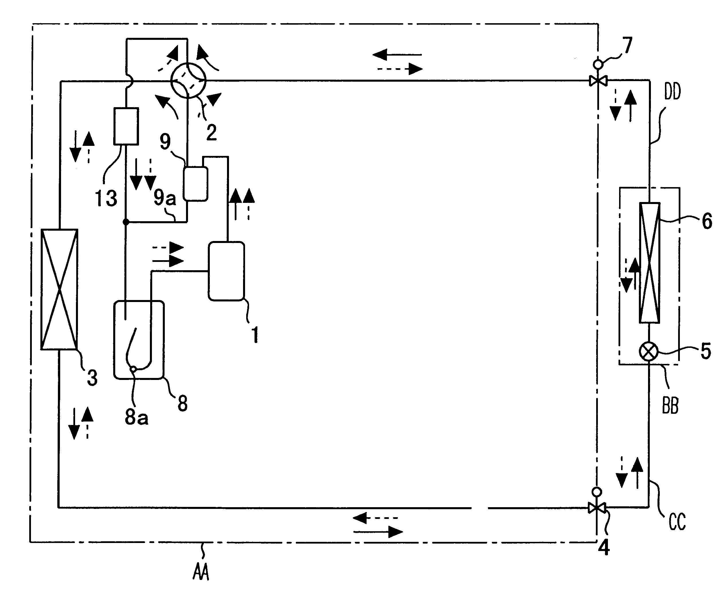
FIG. 1 is a schematic diagram showing a refrigerant circuit of a refrigeration system which effects heat exchange by means of a refrigerant, as an example refrigeration system according to a first embodiment of the present invention.

In FIG. 1, reference symbol AA designates a heat source unit accommodating a compressor 1, a four-way valve 2, a heat exchanger 3 on a heat-source-unit-side , a first control valve 4, a second control valve 7, an accumulator 8, an oil separator 9 (corresponding to oil separation means), and extraneous-matter trapping means 13.

The oil separator 9 is provided in an outlet pipe of the compressor 1 and separates a refrigeration oil which is discharged from the compressor 1 together with a refrigerant. The extraneous-matter trapping means 13 is interposed between the four-way valve 2 and the accumulator 8. Reference numeral 9a designates a bypass channel extending from the bottom of the oil separator 9 to a downstream position relative to the exit of the extr...

second embodiment

FIG. 8 is a schematic diagram showing a refrigerant circuit of a refrigeration system which effects heat exchange by means of a refrigerant, as an example refrigeration system according to a second embodiment of the present invention.

In FIG. 8, reference symbol AA designates a heat source unit accommodating a compressor 1, a four-way valve 2, heat exchangers 3a and 3b on heat-source-unit-side, a first control valve 4, a second control valve 7, an accumulator 8, an oil separator 9 (corresponding to oil separation means), and extraneous-matter trapping means 13.

The oil separator 9 is interposed between an outlet pipe 21 of the compressor 1 and an inlet pipe 22 of the four-way valve 2 for separating a refrigeration oil discharged from the compressor 1 together with a refrigerant and for discharging the thus-separated refrigeration oil to a refrigeration oil return pipe 23. The return pipe 23 is connected to a branch line 25 at a junction 24, and the branch line 25 is connected, by way ...

third embodiment

FIG. 10 is a schematic diagram showing a refrigerant circuit of a refrigeration system, as an example refrigeration system according to a third embodiment of the present invention. In FIG. 10, reference symbols BB to DD, reference numerals 1 through 9, and reference numerals 8a and 9a are the same as those employed in the first embodiment, and hence repetition of their detailed explanations is omitted here.

Reference numeral 12a designates cooling means (a cooling device) for cooling and liquefying a hot, high-pressure gaseous refrigerant; 12b designates heating means (a heating device) for evaporating a low-pressure two-phase refrigerant; 13 designates extraneous-matter trapping means (an extraneous-matter trapping device) provided at the exit of the heating means 12b; 14a designates a first electromagnetic valve disposed at the exit of the extraneous-matter trapping means 13; and 14b designates a second electromagnetic valve disposed at the entrance of the heating means 12b.

Referen...


PUM


Abstract

A heat source unit and refrigerant used in an existing refrigeration system are replaced with new refrigerant and a new heat source unit which employs the new refrigerant and is equipped with an oil separator and extraneous-matter trapping device. An indoor unit of the existing refrigeration system may be used, in its present form, or replaced with a new indoor unit. Further, connecting pipes used for the existing refrigeration are reused. After replacement of refrigerant, the refrigeration system performs an ordinary operation after having performed a cleaning operation. The extraneous-matter trapping device is provided in a refrigerant pipe close to the heat source unit or in a bypass channel connected to the refrigerant pipe close to the heat source unit. Alternatively, only the heat source unit of the existing refrigeration system is replaced with a new one, and there is employed refrigeration oil which has no mutual solubility with respect to HFC or has very low mutual solubility.

Description

1. Field of the InventionThe present invention relates to a method of replacing and operating a refrigeration system or an air conditioning system employing the refrigeration system. Further, the present invention relates to a method of replacing a refrigerant in a refrigeration system.More particularly, the present invention relates to a refrigeration system which employs a refrigeration cycle (hereinafter referred to as a "refrigeration system") and enables replacement of a heat source unit with a new one or replacement of a heat source unit and an indoor unit with new ones and which enables replacement of a previous-employed refrigerant with a new refrigerant of different type without involvement of replacement of at least connecting pipes for connecting the heat source unit with the indoor unit. The present invention further relates to a method of operating such refrigeration system.2. Background ArtFIG. 27 shows a popular standalone-type refrigeration system which has already b...

Claims


Application Information

Patent Timeline
Patent Type & Authority Patents(United States)
IPC IPC(8): F25B13/00F25B47/00F25B45/00F25B31/00
CPCF25B13/00F25B47/00F25B31/002F25B45/00F25B2500/01F25B2313/025F25B2313/0272F25B2313/02741F25B2400/18F25B2313/023
Inventor KASAI, TOMOHIKOKURACHI, MITSUNORITANI, HIDEKAZUMIYAMOTO, MORIYASUMIDA, YOSHIHIROIKEDA, TAKASHIKIKUKAWA, TOSHIHIROMASUDA, SHOHICHIROHKOGE, HIROFUMI
Owner MITSUBISHI ELECTRIC CORP
Why Eureka
Try Eureka