Integrated circuit comparator or amplifier

a comparator and integrated circuit technology, applied in pulse manipulation, pulse technique, instruments, etc., can solve the problems of voltage offset, speed of operation, time delay in operation, and the operation of the comparator becomes slower and less reliabl

Inactive Publication Date: 2003-01-28
MICRON TECH INC
View PDF7 Cites 29 Cited by
  • Summary
  • Abstract
  • Description
  • Claims
  • Application Information

AI Technical Summary

Problems solved by technology

Two primary concerns in the application of comparators are the mismatch of transistor characteristics, resulting in voltage offsets, and the speed of operation, or time delay in operation.
Because one of the basic components of a comparator is a differential amplifier, which typically involves three transistors coupled in series, operation of the comparator becomes slower and less reliable as power supply voltages are reduced.
If the excess of gate-to-source voltage above threshold (VGS-VT) is small, the delay time will be long, and the circuits will operate at low switching speeds.

Method used


Image

  • Integrated circuit comparator or amplifier
  • Integrated circuit comparator or amplifier
  • Integrated circuit comparator or amplifier

Examples


Embodiment Construction

Illustrative embodiments of the invention are described below. In the interest of clarity, not all features of an actual implementation are described in this specification. It will of course be appreciated that in the development of any such actual embodiment, numerous implementation-specific decisions must be made to achieve the developers' specific goals, such as compliance with system-related and business-related constraints, which will vary from one implementation to another. Moreover, it will be appreciated that such a development effort might be complex and time-consuming, but would nevertheless be a routine undertaking for those of ordinary skill in the art having the benefit of this disclosure.

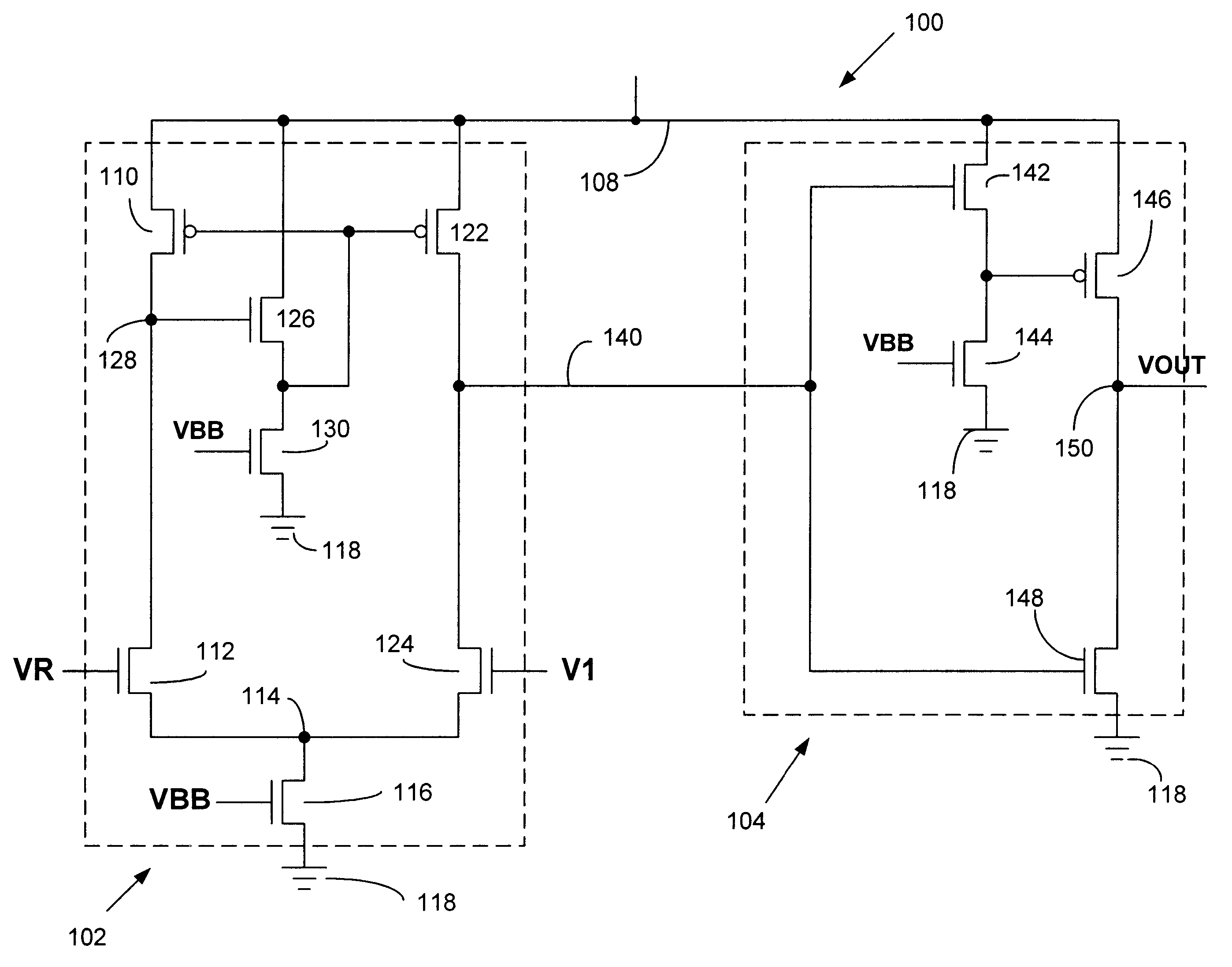
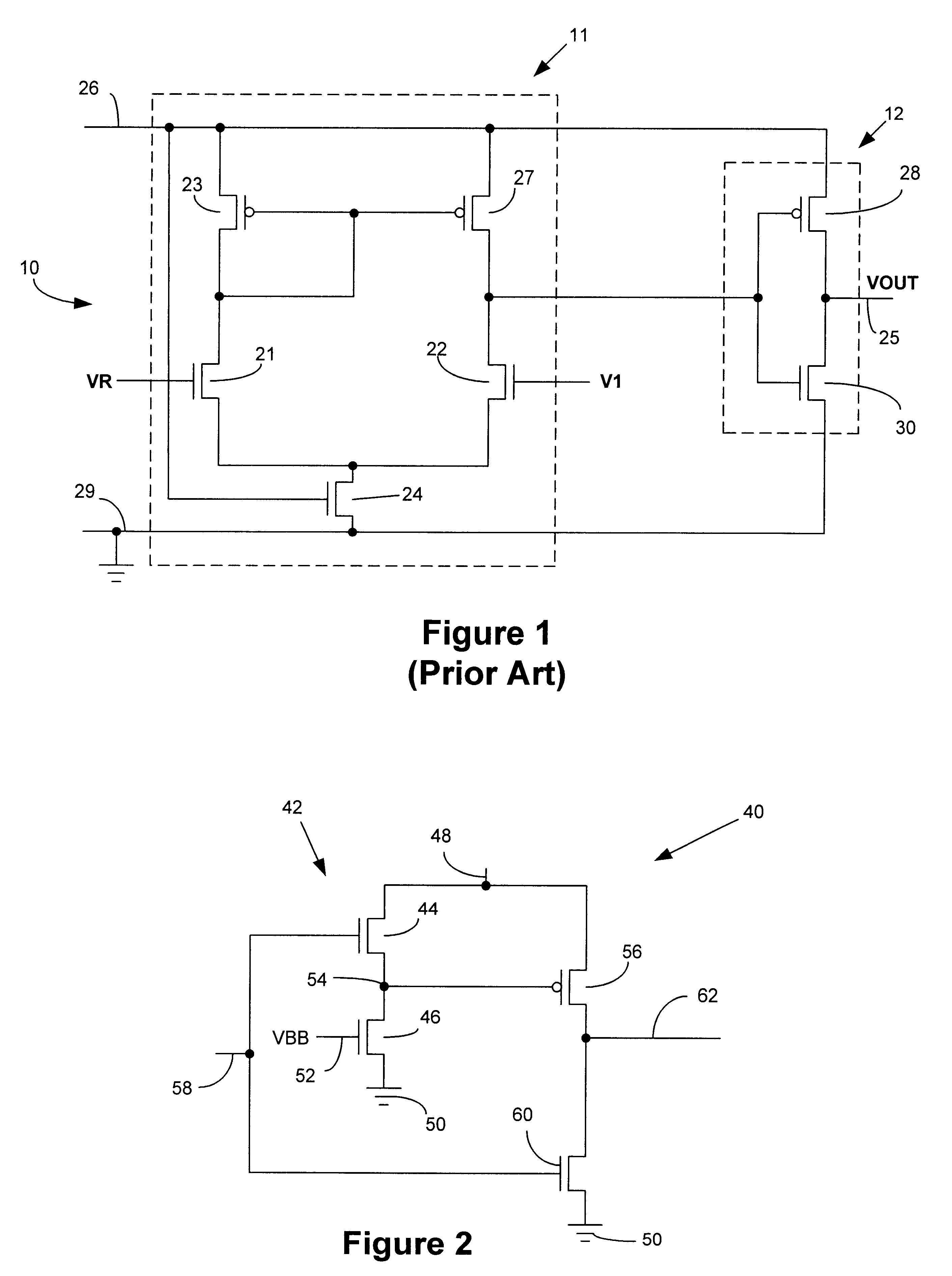
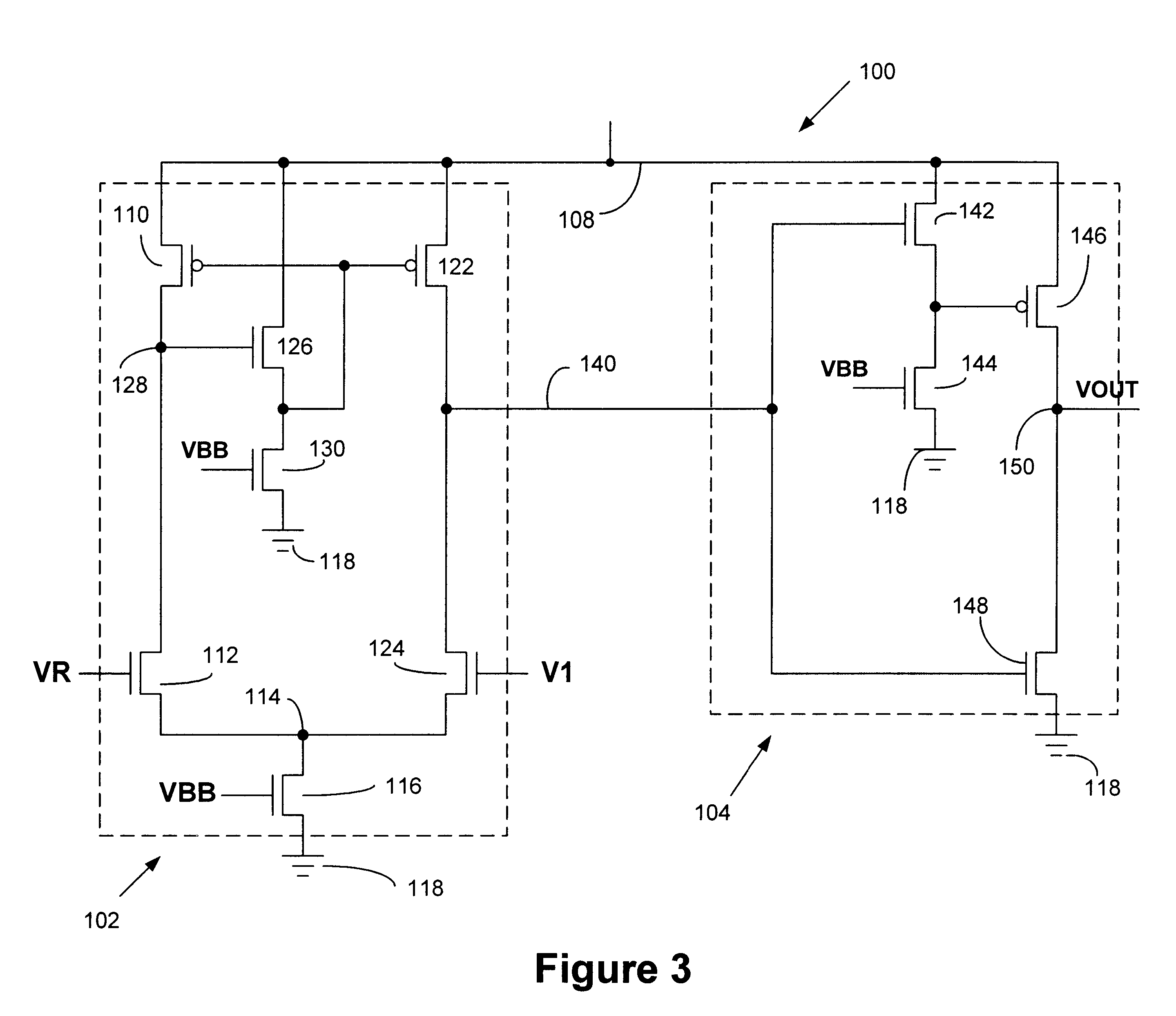
The present invention will now be described with reference to FIGS. 2-4. In general, the present invention is directed to a comparator circuit useful in low voltage applications. The illustrative embodiments shown in FIGS. 2-4 and described herein utilize n-channel and p-channel transi...


PUM


Abstract

An integrated circuit comparator includes a differential amplifier, a source follower circuit coupled to a gate terminal of a first transistor in the differential amplifier, and an output circuit. One or more source follower circuits may be utilized in connection with the differential amplifier, and one or more source follower circuits may be utilized in connection with the output circuit.

Description

1. Field of the InventionThe present invention relates generally to integrated circuit comparators, and, more particularly, to integrated circuit comparators for use in low voltage applications.2. Description of the Related ArtA conventional CMOS voltage comparator 10 is illustrated in FIG. 1. The CMOS voltage comparator 10 includes a differential amplifier II and an inverter 12. A reference voltage VR is applied to one input of the differential amplifier 11, i.e., a gate terminal of a transistor 21, and an input voltage V1 to be compared to the reference voltage is applied to another input to the differential amplifier 11, i.e., a gate terminal of a transistor 22. In operation, when the input voltage V1 becomes higher than the reference voltage VR, an output signal on a line 25 switches from a low voltage, for example, a logic level "zero," to a high voltage, for example, a logic level "one." When the input voltage V1 becomes lower than the reference voltage VR, the transistor 22 t...

Claims


Application Information

Patent Timeline
Patent Type & Authority Patents(United States)
IPC IPC(8): H03K5/22H03K5/24
CPCH03F3/45183H03K5/2481H03K5/2472H03F2200/513H03F2200/78H03F2203/45666H03F2203/45664
Inventor FORBES, LEONARD
Owner MICRON TECH INC
Why Eureka
Try Eureka