Adjustment mechanism

a technology of adjustment mechanism and adjustment mechanism, which is applied in the direction of metal sawing device, metal sawing apparatus, manufacturing tools, etc., can solve the problems of requiring significant effort on the part of the operator, and the majority of the adjustment mechanism is deficient in some respect, so as to improve the design of the adjustment mechanism, improve the effect of positioning accuracy, and improve the effect of adjusting mechanism

Inactive Publication Date: 2003-02-04
BLACK & DECKER INC
View PDF26 Cites 67 Cited by
  • Summary
  • Abstract
  • Description
  • Claims
  • Application Information

AI Technical Summary

Benefits of technology

A specific example of a cutting device having the foregoing arrangement of elements is a power operated miter saw. Miter saws commonly include a table portion that is rotatable relative to the base portion to thereby allow the saw blade to change orientation relative to the workpiece guide of the miter saw. Adjustment of the orientation of the table portion relative to the base portion allows the saw blade to execute cuts at various miter angles through a workpiece supported by the workpiece guide.
Accordingly, it will be appreciated that there is a need to improve the design of adjustment mechanisms for accurately positioning and releasably locking the table portion of a miter saw or other similarly constructed cutting or abrading device relative to the base portion of the device. In particular, it would be advantageous to provide an adjustment mechanism by which the orientation of the rotatable table portion of a miter saw or the like may be quickly and easily repositioned and locked relative to other elements of the device such a mechanism would allow for rapid and precise adjustment and locking of the angle of the cutting member relative to the device's workpiece guide. More broadly, it would be advantageous to provide an improved adjustment mechanism for adjusting and locking a position of a first surface of a woodworking, metal working, or other device relative to other elements of the device.

Problems solved by technology

However, most of these adjustment mechanisms are deficient in some respect.
Such mechanisms generally require significant effort on the part of the operator to generate a frictional force that is sufficient to suitably fix the table portion relative to the base portion.

Method used


Image

  • Adjustment mechanism
  • Adjustment mechanism
  • Adjustment mechanism

Examples


Embodiment Construction

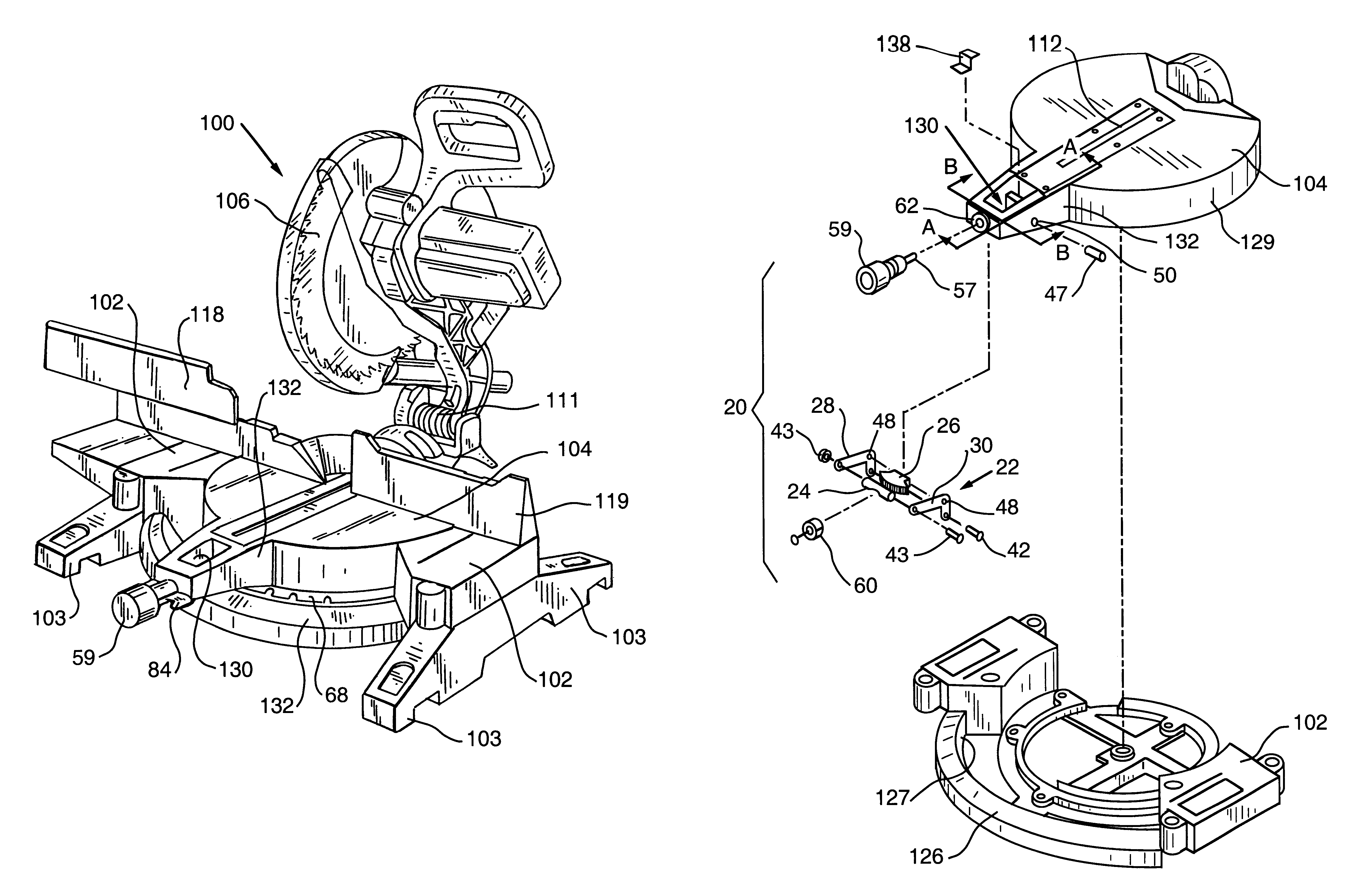
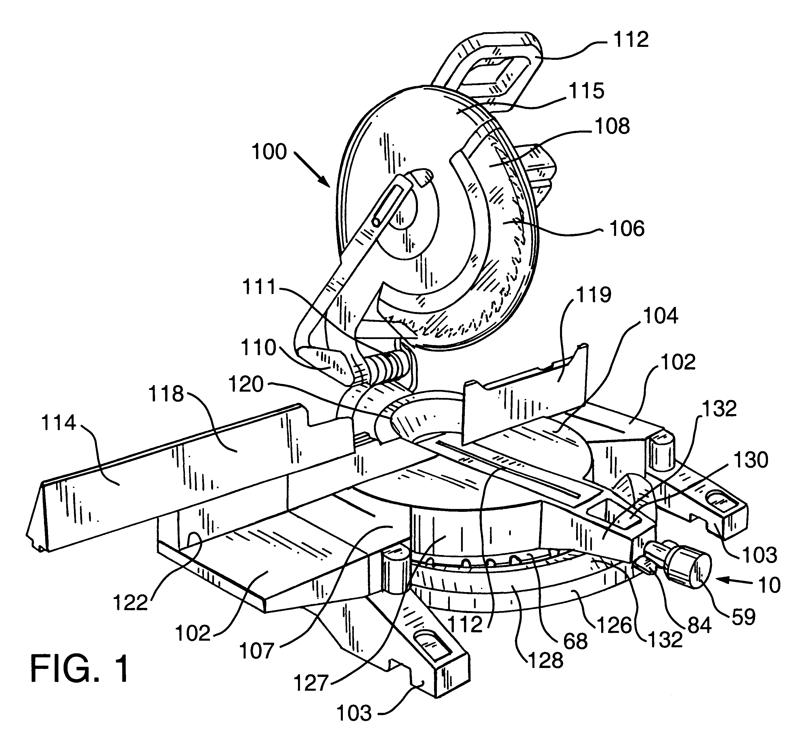
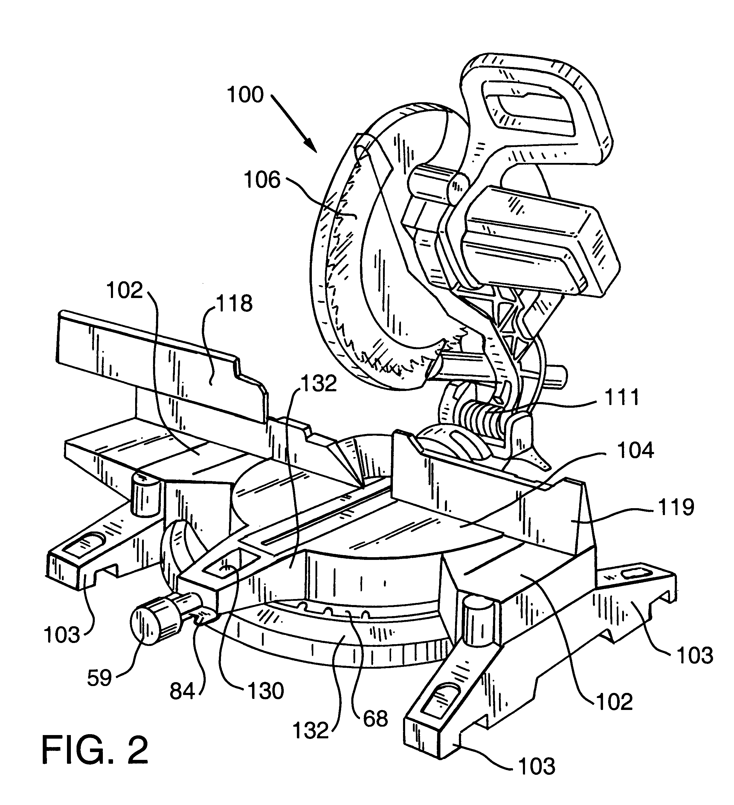
The present invention is susceptible of embodiment in many different forms. This specification and the accompanying drawings provide only certain specific embodiments as examples of the invention. The invention is not intended to be limited to the embodiments so described, and the actual scope of the invention is better indicated by the appended claims. The adjustment mechanism of the present invention may be incorporated into certain otherwise conventional cutting and / or abrading devices, such as miter saws, and other devices. The details of those conventional devices, although not fully described or illustrated herein, will be apparent to those having ordinary skill in the art and may not be described herein.

Referring now to the drawings for the purpose of illustrating embodiments of the invention only and not for the purpose of limiting the same, FIGS. 1-29 generally show aspects of one embodiment of the present invention in the form of an adjustment mechanism 10 incorporated int...


PUM

PropertyMeasurementUnit
diameteraaaaaaaaaa
miter anglesaaaaaaaaaa
angleaaaaaaaaaa

Abstract

Apparatus for releasably adjusting a position of a first portion of a device relative to a second portion of the device. The first portion includes a first surface, and the second portion includes a second surface. A workpiece support surface is defined by the first and second surfaces, and the first surface is rotatable relative to the second surface. A locking mechanism is provided to selectively restrain rotation of the first surface relative to the second surface. An indexing mechanism optionally is provided including a detent mechanism which selectively restrains rotation of the first surface relative to the second surface in one of a plurality of predetermined positions.

Description

FEDERALLY SPONSORED RESEARCHNot applicable.TECHNICAL FIELD AND INDUSTRIAL APPLICABILITY OF THE INVENTIONThe present invention relates to adjustment mechanisms and, more particularly, to mechanisms for adjustment and locking of the workpiece support surface of devices, such as, for example, woodworking and metal working devices. The present invention may be adapted for use with any device having one or more support surfaces that may be adjusted in orientation relative to one or more other elements of the device. Examples of possible applications of the adjustment mechanism of the present invention include use of the invention as a mean for adjusting and locking the orientation of the rotatable workpiece support surface of a power operated miter saw.DESCRIPTION OF THE INVENTION BACKGROUNDA number of known cutting devices include a driven cutting member such as, for example, a circular saw blade, and a generally planar workpiece support surface. In such devices, the workpiece support s...

Claims


Application Information

Patent Timeline
Patent Type & Authority Patents(United States)
IPC IPC(8): B23D47/02B23D45/04B23D47/00B23D45/00B27G5/02B27G5/00
CPCB23D45/044B27G5/02B23D47/025B27B5/29Y10T83/7697Y10T83/7726Y10T83/7788Y10T83/8773
Inventor YOUNG, RONALD E.
Owner BLACK & DECKER INC
Why Eureka
Try Eureka